Structure of test cavity

A test chamber and transducer technology, applied in the field of test chamber structure, can solve the problems of high sensor detection limit value, large sensor detection error, and long sensor response time, so as to promote practicality and popularization, reduce detection error, and improve The effect of detection accuracy

Inactive Publication Date: 2012-09-12
UNIV OF ELECTRONICS SCI & TECH OF CHINA
View PDF13 Cites 7 Cited by
  • Summary
  • Abstract
  • Description
  • Claims
  • Application Information

AI Technical Summary

Problems solved by technology

However, the defects of the sensor itself limit its large-scale application. The main defects are: 1. The response time of the sensor is too long; 2. The detection error of the sensor is relatively large, especially when detecting low-concentration gases, which directly affects the detection accuracy. ;3. The detection limit value of the sensor is too high to meet the demand
The above problems are the biggest problems in the practical application of sensors

Method used


Image

  • Structure of test cavity
  • Structure of test cavity
  • Structure of test cavity

Examples


Embodiment Construction

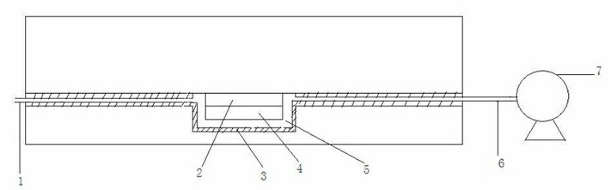
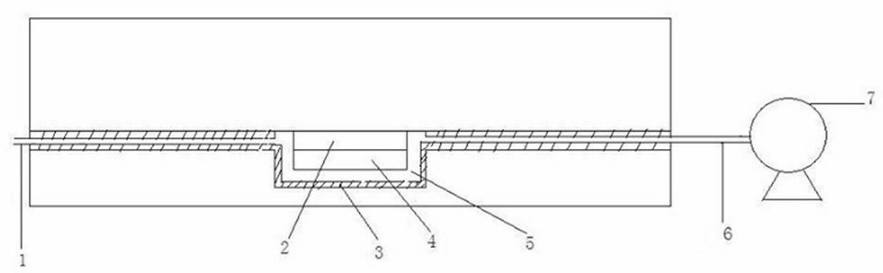
[0026] The present invention will be further described below in conjunction with the accompanying drawings and specific embodiments.

[0027] A test chamber structure, including an airflow inlet, a transducer, an inner wall medium layer, a sensitive film, a test chamber, an airflow outlet, and an air pump. The test chamber and the air pump are connected through capillary tubes to reduce the inflated volume inside the test chamber. The three-dimensional At least one dimension is on the order of microns, and the cross-sectional size of the gas path connecting the outside world and the test chamber is on the order of microns to millimeters. The transducer is a part of the inner wall of the test cavity or is arranged in the test cavity. The material of the capillary is one of semiconductor materials such as silicon, silicon dioxide, gallium arsenide, and silicon nitride. The inner wall medium layer of the test chamber is made of low surface tension and chemically inert material o...


PUM


Abstract

The invention discloses a structure of a test cavity in the technical field of a gas sensor. The structure of the test cavity comprises an airflow inlet 1, an energy converter 2, an inner wall medium layer 3, a sensitive membrane 4, a test cavity 5, an airflow outlet 6 and an air pump. The test cavity is connected with the air pump through a capillary tube. With the adoption of the structure provided by the invention, the inflation volume inside the test cavity is reduced. At the same airflow, the air concentration which is close to the sensitive membrane 4 is rapidly changed, and the energy converter can achieve a stable state in a rapider manner, so that the response time of the energy converter is shortened. An area of the inner wall of the test cavity is reduced, so that the amount of absorbing the air to be detected through the inner wall is reduced. Furthermore, the absorption amount of substances to be detected through the area of the inner wall in a unit is reduced by selecting a material of the inner wall which difficultly adsorbs the air to be detected or coating the medium material on the inner wall, so that the detection precision is improved and the detection limitation value is reduced.

Description

technical field [0001] The invention relates to the technical field of gas sensors, in particular to a test cavity structure. Background technique [0002] Gas sensors have good application prospects in indoor air quality detection, industrial environment detection, food industry detection, battlefield environment early warning, anti-terrorism early warning and other fields. After integration with the Internet of Things, the quality and efficiency of social production and life can be greatly improved. However, the defects of the sensor itself limit its large-scale application. The main defects are: 1. The response time of the sensor is too long; 2. The detection error of the sensor is relatively large, especially when detecting low-concentration gases, which directly affects the detection accuracy. ; 3. The detection limit of the sensor is too high to meet the demand. [0003] At present, there are two main reasons for the long response time of the sensor: one is that the s...

Claims


Application Information

Patent Timeline
Patent Type & Authority Applications(China)
IPC IPC(8): G01N33/00
Inventor 谢光忠蒋亚东周泳杜晓松李娴太惠玲朱涛廖剑
Owner UNIV OF ELECTRONICS SCI & TECH OF CHINA
Why Eureka
Try Eureka