
System and method for automatically recording geometric parameters of numerical-control tools

A technology of geometric parameter and automatic input, applied in general control system, control/regulation system, program control and other directions, can solve the problems of low work efficiency, tool damage, high error probability, etc., to improve work efficiency, less input data, The effect of high safety

Inactive Publication Date: 2012-09-12
CHONGQING UNIV
View PDF3 Cites 13 Cited by
  • Summary
  • Abstract
  • Description
  • Claims
  • Application Information

AI Technical Summary

Problems solved by technology

[0003] The manual entry of tool geometric parameters has the following disadvantages: First, the process is cumbersome and inefficient: the worker needs to take out the tool from the machine tool first, then read the tool parameters on the tool setting instrument, and manually copy or print out the tool setting instrument. The tool parameter data, and finally enter the corresponding tool parameters on the operation panel of the CNC machine tool
In this mode of operation, the process is cumbersome and there are many types of tools, resulting in low work efficiency and heavy workload for workers.
Second, the probability of error is high, which may lead to processing accidents: the number of parameters input in the tool setting instrument is large, and the manual input method will greatly increase the error probability, which may cause inaccurate and out-of-sync tool parameters
What's more serious is that if you misread the number of decimal places in the parameters during manual entry, the difference between the tool size parameters entered into the CNC machining center on the machine panel and the actual parameters is too large, which will cause tool damage or even cause machining accidents.

Method used


Image

  • System and method for automatically recording geometric parameters of numerical-control tools
  • System and method for automatically recording geometric parameters of numerical-control tools

Examples


Embodiment

[0030] In this embodiment, the geometric parameters of the tool are tool length and tool diameter. Both the tool length compensation and the tool diameter compensation adopt the positive compensation method. The reference coordinates of the tool setting are both set to 0, and the measurement unit is mm.

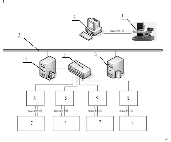
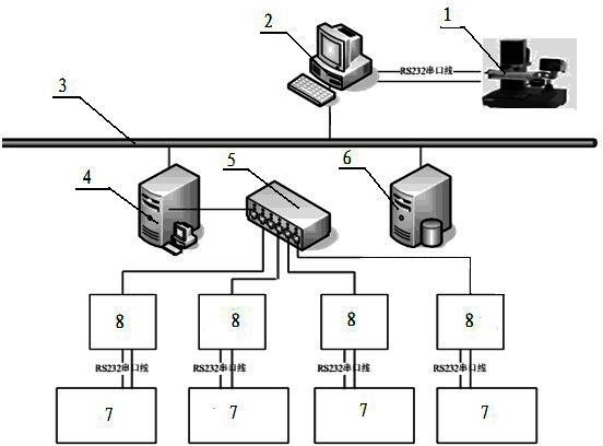
[0031] Automatic input system of CNC tool geometric parameters: Digital tool setting instrument 1 adopts TC100 tool setting instrument produced by Swiss PWB company, and uses RS232 serial port line to connect the serial port marked with serial interface data cable E-Pro II on digital tool setting instrument 1 and industrial The COM1 serial port of the computer 2 is connected, the industrial computer 2 is connected with the DNC server 4 and the CNC tool management system 6 through the Ethernet network 3, the DNC server 4 is connected with the DNC intelligent terminal 8 through the Ethernet network 3, and the DNC intelligent terminal 8 is connected through The RS232 serial port ...


PUM


Abstract

The invention relates to the technical field of numerical-control machining and discloses a system and a method for automatically recording geometric parameters of numerical-control tools. The method includes that an industrial computer transmits tool geometric parameters acquired by a numerical tool setter to a numerical-control tool management system; the numerical-control tool management system analyzes tool geometric parameters, tool codes and numerical-control machining center codes corresponding to the tools from received data, converts tool geometric parameters and tool codes into a text corresponding to the numerical-control machining center codes and identifiable by the numerical-control system according to the numerical-control machining center codes, and transmit the text to a DNC (direct numerical control) server; a numerical-control machining center downloads the text identifiable by numerical-control system types of the numerical-control machining center from the DNC server, analyzes the text and updates data corresponding to the tools according to acquired data analyzed. During the whole recording process of the tool geometric parameters, the tool codes and the numerical-control machining center codes are recorded only during tool aligning, so that recorded data are few, work efficiency is improved, error is small and safety is high.

Description

technical field [0001] The invention relates to the technical field of numerical control machining, in particular to a system and method for automatically inputting geometric parameters of numerical control tools. Background technique [0002] In the field of CNC machining technology, the current method for entering geometric parameters of tools on CNC machine tools in enterprises is generally: first use a tool setting instrument to perform tool setting, read the geometric parameter information of the tool, and then use manual input. The operation panel input to the CNC machine tool. Tool geometry parameters mainly include: tool length, diameter, tool nose arc radius, entering angle, deviation of turning tool tip from the center of the part, etc. [0003] The manual entry of tool geometric parameters has the following disadvantages: First, the process is cumbersome and inefficient: the worker needs to take out the tool from the machine tool first, then read the tool paramet...

Claims


Application Information

Patent Timeline
Patent Type & Authority Applications(China)
IPC IPC(8): G05B19/408
Inventor 徐玲王时龙郑飞杨梦宁张小洪洪明坚葛永新杨丹
Owner CHONGQING UNIV
Learn More