Touch representation device based on electrostatic force

A technology of tactile reproduction and electrostatic force, applied in the direction of electrical digital data processing, input/output process of data processing, input/output of user/computer interaction, etc., can solve problems such as poor applicability, difficulty in miniaturization, and large and complex systems , to achieve the effect of strong applicability, low device cost and high flexibility

Inactive Publication Date: 2012-09-12
孙晓颖
View PDF7 Cites 48 Cited by
  • Summary
  • Abstract
  • Description
  • Claims
  • Application Information

AI Technical Summary

Problems solved by technology

[0003] At present, most of the tactile reproduction technologies are based on mechanical force. Typical devices include the needle-type contact array developed by Yasushi Ikei et al. in Japan, the gas pressure tactile reproduction device developed by Naoya Asamura et al. The tactile reproduction device based on the sawtooth surface developed by Nara et al. However, due to the bulky equipment, it is difficult to apply and promote it in daily life. The electrostatic tactile reproduction technology is currently generally considered to be the most important way to realize the miniaturization of the tactile reproduction system. The latest technology in the field
[0004] In 2011, Ivan Poupyrev et al. disclosed a tactile reproduction interaction technology based on electric vibration in the US patent US 2011 / 0285667 A1 entitled "Electrovibration for Touch Surfaces". Reproduction of tactile sensation, introduces the working principle of tactile interactive screen, not a complete tactile reproduction device
In 2011, Kajimoto Hiroyuki et al. disclosed an electrical stimulation-based device and electrical stimulation method in the Japanese patent WO 2011 / 155089 A1 entitled "Electrical Stimulation Device and Electrical Stimulation Method", but the system is huge and complex, and it is difficult to miniaturize. poor applicability

Method used


Image

  • Touch representation device based on electrostatic force
  • Touch representation device based on electrostatic force
  • Touch representation device based on electrostatic force

Examples


Embodiment Construction
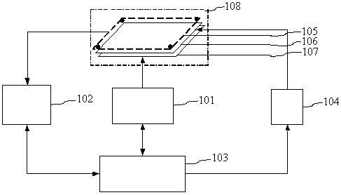
[0033] include:

[0034] (1) Electrostatic force tactile reproduction interactive screen 108, including an optical sensing unit 105, electrostatic force tactile reproduction panel 106, and LCD display panel 107, used for user's interactive operation on the electrostatic force tactile reproduction device,

[0035] (2) Finger trajectory tracking unit 102, including a processor 10201 and a communication interface 10202, used to calculate the position coordinates of the finger after acquiring image information;

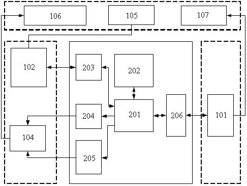
[0036] (3) The electrostatic force tactile reproduction controller 103 is composed of a processing unit 201, a memory 202, a position detection interface 203, a D / A converter 204, a signal gain control interface 205, and a USB communication interface 206 for real-time processing of the tactile reproduction algorithm, transmitting The driving signal is responsible for communicating with the PC 101 to control the work of the entire system;

[0037] (4) The signal driving u...


PUM


Abstract

The invention relates to a touch representation device based on electrostatic force, belonging to a touch representation device. The touch representation device comprises an electrostatic force touch representation interactive screen, a finger trace tracking unit, an electrostatic force touch representation controller, a signal driving unit and a PC (Personal Computer). The finger trace tracking unit detects a finger position, and maps a touch force representation method of a visual object at the position; an electric signal parameter for representing a touch force is generated according to the corresponding relation between an electric signal and the touch force; a driving signal is output; the driving signal is amplified; and the amplified driving signal acts on the electrostatic force touch representation interactive screen to cause skin deformation of a finger so as to sense an absorption force and a repelling force, thereby realizing touch representation. The touch representation device has the advantages of low cost, high flexibility and strong applicability, and can realize the touch representation function on a small mobile terminal.

Description

technical field [0001] The invention belongs to a tactile reproduction device. Background technique [0002] Efficient and natural tactile reproduction technology can enhance the immersion and realism of virtual reality, provide a more real and direct interactive experience, and push the communication between human beings and the virtual world to a new stage. It is currently a hot spot in the field of virtual reality. The tactile reproduction technology plays an important auxiliary role in science education, industrial design, picture viewing for the blind, and telemedicine. [0003] At present, most of the tactile reproduction technologies are based on mechanical force. Typical devices include the needle-type contact array developed by Yasushi Ikei et al. in Japan, the gas pressure tactile reproduction device developed by Naoya Asamura et al. The tactile reproduction device based on the sawtooth surface developed by Nara et al. However, due to the bulky equipment, it is di...

Claims


Application Information

Patent Timeline
Patent Type & Authority Applications(China)
IPC IPC(8): G06F3/01G06F3/042
Inventor 孙晓颖伍荣福王庆龙燕学智陈建王波温泉
Owner 孙晓颖
Why Eureka
Try Eureka