Zero-refraction microwave lens based on electromagnetic double resonance structure

A microwave lens and double-resonance technology, applied in the direction of electrical components, antennas, etc., can solve the problem of low antenna gain improvement effect, achieve the effect of reducing the refractive index, good impedance matching characteristics, and reducing the widening frequency band

Inactive Publication Date: 2012-09-12
HARBIN INST OF TECH
View PDF6 Cites 4 Cited by
  • Summary
  • Abstract
  • Description
  • Claims
  • Application Information

AI Technical Summary

Problems solved by technology

[0003] The purpose of the present invention is to solve the problem that the current anisotropic zero-refraction lens has a low effect on improving the antenna gain, and proposes a zero-refraction microwave lens based on an electromagnetic double-resonance structure

Method used


Image

  • Zero-refraction microwave lens based on electromagnetic double resonance structure
  • Zero-refraction microwave lens based on electromagnetic double resonance structure
  • Zero-refraction microwave lens based on electromagnetic double resonance structure

Examples


specific Embodiment approach 1

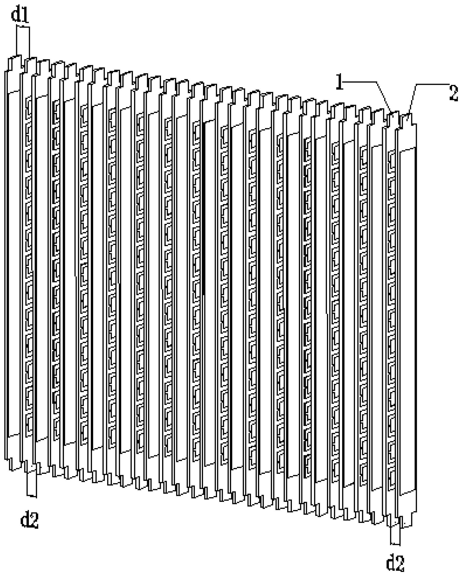
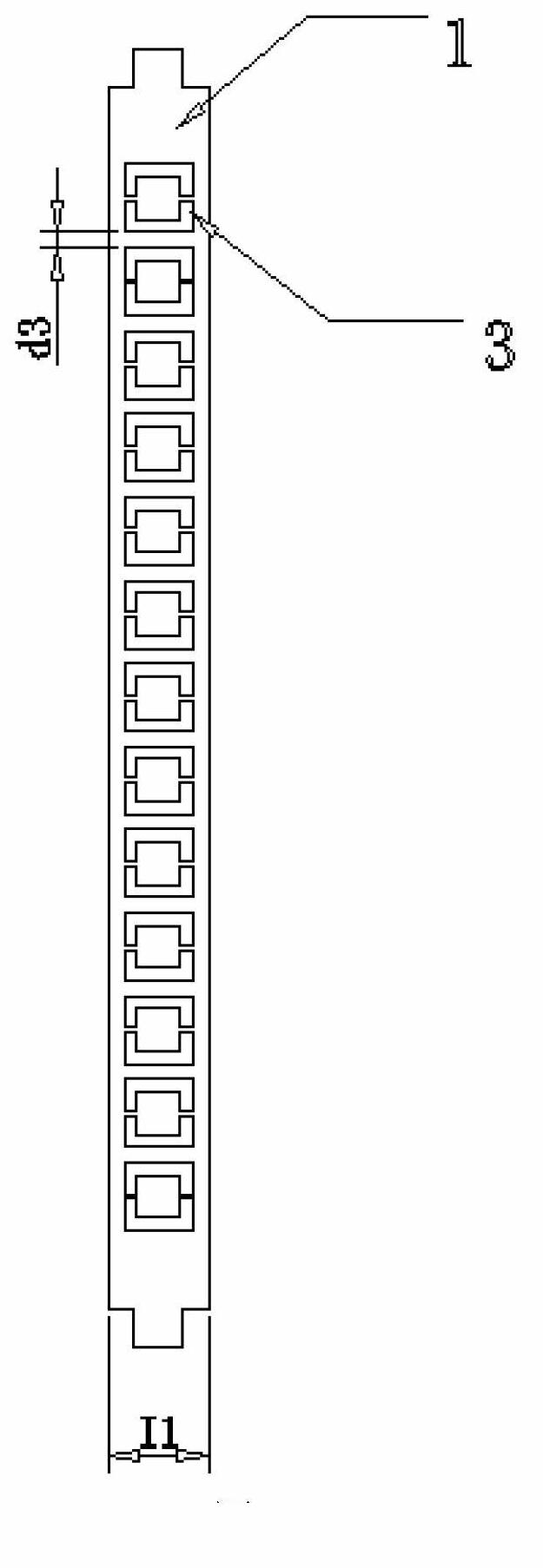
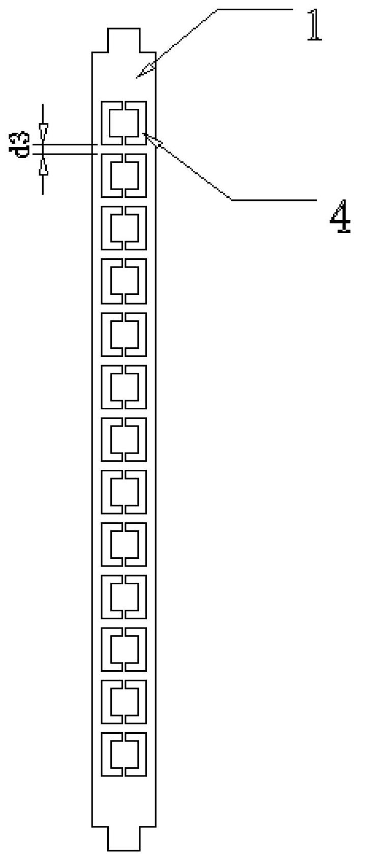
[0020] Specific implementation mode one: combine figure 1 , figure 2 , image 3 , Figure 4 with Figure 5 Describe this embodiment, the zero-refraction microwave lens based on the electromagnetic double resonance structure of the present invention, it includes N first strip-shaped dielectric substrates 1 and N+1 second strip-shaped dielectric substrates 2, and N+1 second strip-shaped dielectric substrates 2 Shaped dielectric substrate 2 and N first strip-shaped dielectric substrates 1 are arranged alternately and parallel to each other, and the first strip-shaped dielectric substrate 1 and the second strip-shaped dielectric substrate 2 have the same shape;

[0021] The distances between the adjacent N first strip-shaped dielectric substrates 1 and the N+1 second strip-shaped dielectric substrates 2 are d1, d2, d1, d2...d2 respectively;

[0022] The first strip-shaped dielectric substrate 1 is formed by etching a double-sided copper-clad strip-shaped dielectric substrate...

specific Embodiment approach 2

[0025] Specific implementation mode two: combination figure 2 This embodiment is described. This embodiment is a further description of the zero-refraction microwave lens based on the electromagnetic double-resonance structure described in Embodiment 1. The d1 is 2.9 mm, and the d2 is 3.7 mm.

specific Embodiment approach 3

[0026] Embodiment 3: This embodiment is a further description of the zero-refraction microwave lens based on the electromagnetic double resonance structure described in Embodiment 2. The distance d3 between the adjacent square split resonator rings SRR of the first strip-shaped dielectric substrate 1 is 1.2mm.


PUM


Abstract

Enclosed is a zero-refraction microwave lens based on an electromagnetic double resonance structure. The zero-refraction microwave lens based on the electromagnetic double resonance structure is used for solving a problem of poor improvement effect of the existing zero-refraction lens with anisotropy to the antenna gain. N+1 secondary strip-type dielectric substrates and N primary strip-type dielectric substrates are alternately arranged in a mutually parallel manner at distances of d 1, d 2, d 1, d 2......d2. The primary strip-type dielectric substrates are etchingly made of the strip-type dielectric substrates with both sides coated with copper. A plurality of split ring resonators SRR with square openings are etched on both surfaces of each strip-type dielectric substrate and arranged along the longitudinal direction of each strip-type dielectric substrate. The shapes of the split ring resonators SRR with the square openings on one surface of each strip-type dielectric substrate are formed by rotating the split ring resonators SRR with the square openings on the other surface of each strip-type dielectric substrate around the center of the strip-type dielectric substrate. The secondary strip-type dielectric substrates 2 are etchingly made of the strip-type dielectric substrates with single sides coated with copper. The zero-refraction microwave lens based on the electromagnetic double resonance structure is used for assisting to increase the antenna gain.

Description

technical field [0001] The invention relates to a zero-refraction microwave lens, in particular to a zero-refraction microwave lens based on an electromagnetic double resonance structure. Background technique [0002] Metamaterial is a new type of artificial material obtained by periodically or non-periodically arranging basic units with specific geometric shapes. By changing the structure and parameters of the basic unit, the electromagnetic properties of the meta-medium, namely its permittivity and permeability, can be freely controlled. The current permittivity and permeability of supernormal media can be positive, negative or zero, and the two can have the same sign or different signs. Therefore, if a metamaterial with zero permittivity or permeability is constructed, the refractive index of the metamaterial can be zero, that is, a zero refractive index material (ZIM or Zero Refractive Index Metamaterial). In 2002, S.Enoch et al. pointed out that zero-refraction materi...

Claims


Application Information

Patent Timeline
Patent Type & Authority Applications(China)
IPC IPC(8): H01Q15/08
Inventor 孟繁义吕玥珑杨国辉张狂傅佳辉吴群华军
Owner HARBIN INST OF TECH
Why Eureka
Try Eureka