
Video buffer method for receiving end of network video service system

A service system, video buffering technology, applied in the direction of image communication, selective content distribution, electrical components, etc., can solve the problem of inability to adjust the buffer area size and video playback rate, high bandwidth cost, buffer mechanism can not effectively play the advantages and functions, etc. problem, to achieve the effect of adaptive bandwidth playback and high coherence

Inactive Publication Date: 2012-09-12
SHANDONG COMP SCI CENTNAT SUPERCOMP CENT IN JINAN
View PDF6 Cites 21 Cited by
  • Summary
  • Abstract
  • Description
  • Claims
  • Application Information

AI Technical Summary

Problems solved by technology

The above three solutions have their own limitations. Increasing network bandwidth itself cannot meet the individual requirements of different users, and the cost of bandwidth itself is relatively high; using P2P technology can optimize network usage efficiency as a whole, but it cannot guarantee that each Video continuity at the data receiving end; the use of compression technology cannot fundamentally solve the problem of insufficient bandwidth, and will reduce the quality of the video itself
[0005] In the existing field of video buffering, less attention is paid to the inconsistency of the bandwidth environment of different video receiving users, resulting in the lack of personalized features of the buffering module, which cannot automatically adjust the size of the buffering area and video playback rate according to different network environments, so that the buffering mechanism Unable to effectively utilize its own strengths and functions

Method used


Image

  • Video buffer method for receiving end of network video service system
  • Video buffer method for receiving end of network video service system
  • Video buffer method for receiving end of network video service system

Examples


Embodiment Construction

[0019] The present invention will be further described below in conjunction with the accompanying drawings and embodiments.

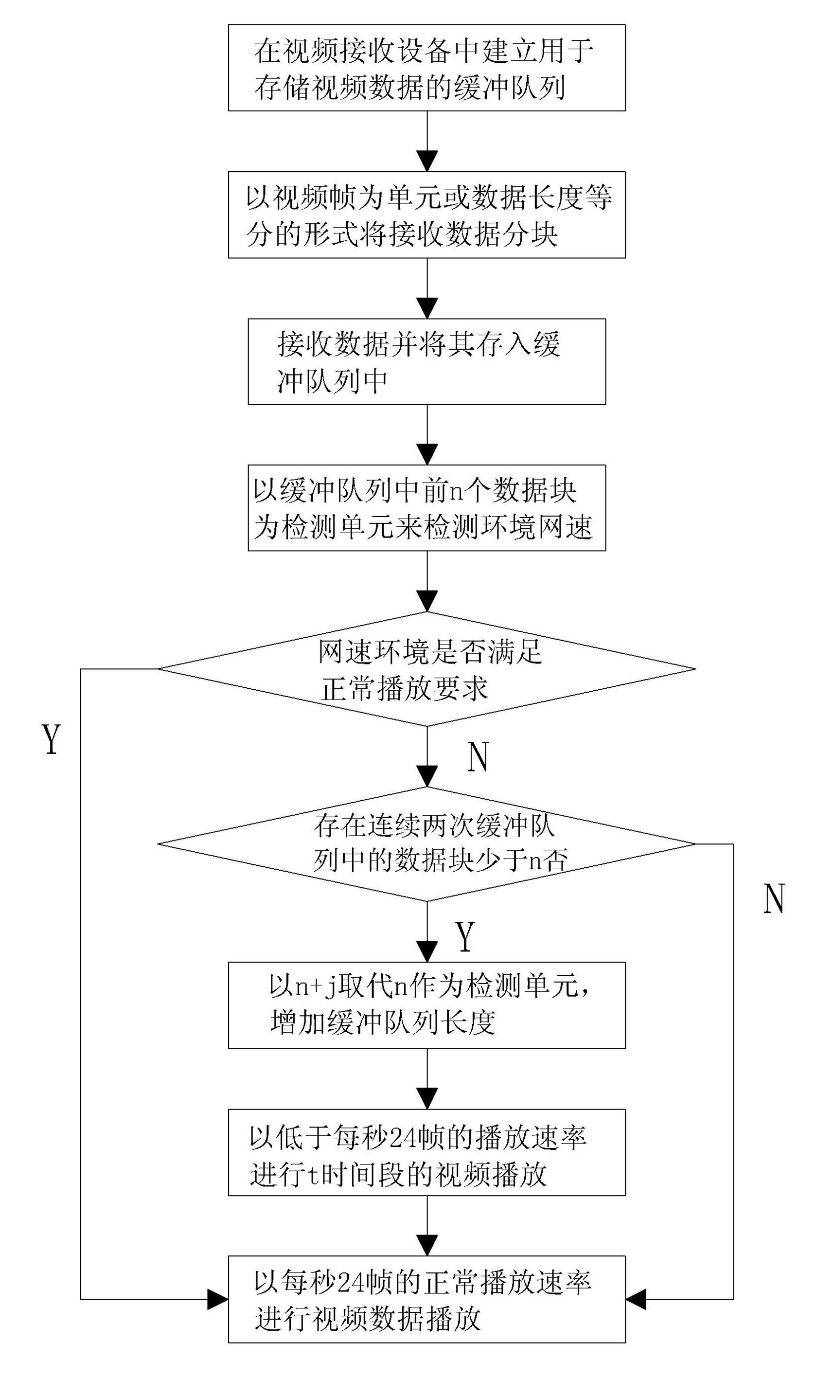
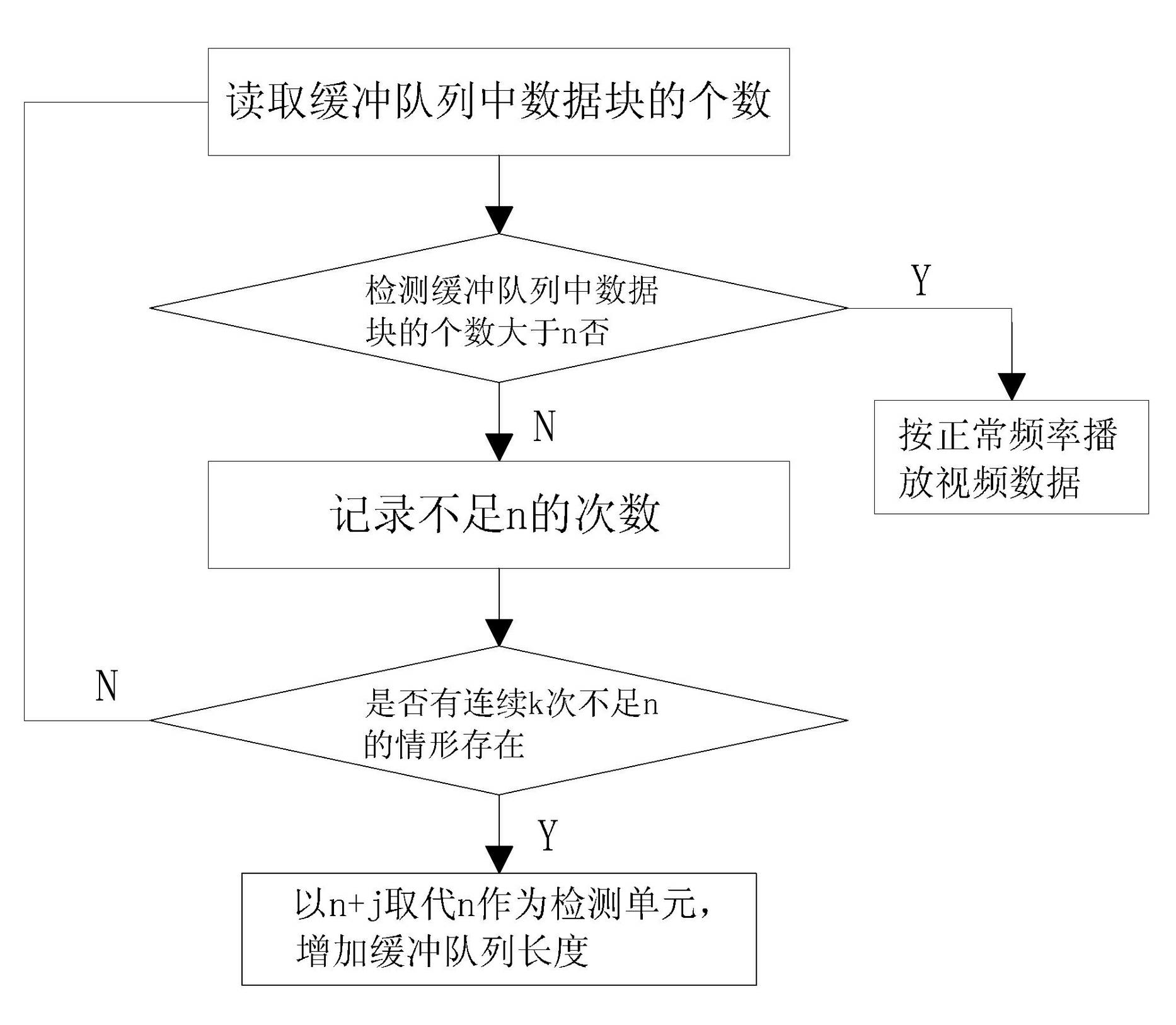
[0020] Such as figure 1 with figure 2 As shown, the video buffering method of the present invention and the flow chart of the method for judging whether to increase the length of the detection unit are given, and the video buffering method of the present invention will be described in detail below in combination with these two flow charts.

[0021] The video buffering method of the receiving end of the network video service system of the present invention comprises the following steps:

[0022] a. Establish a buffer queue, set up a buffer queue for storing video data in the video receiving and playing device, so as to store the video data to be played; the buffering queue is established in the memory of the video receiving and playing device, and it can adopt the form of first-in-first-out The data structure in the form of an array or a linked list s...


PUM


Abstract

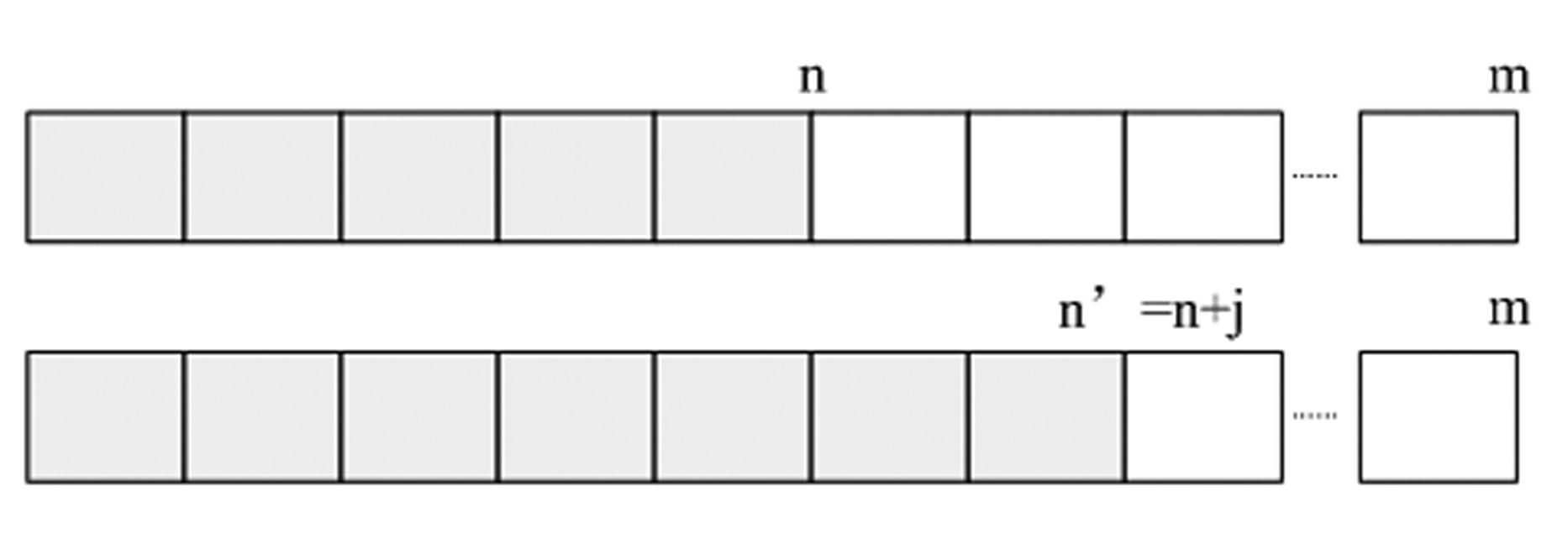
The invention discloses a video buffer method for the receiving end of a network video service system. The method comprises the following steps of: (a), establishing a buffer queue; (b), receiving and blocking data; (c), storing the data into the buffer queue; (d), comparing the receiving and play time of each of the first n data blocks to judge current network speed; (e), if the network speed is high enough, playing the data according to a normal rate; (f), if the network speed is not high enough, performing further judgment; and (g), lowering a play rate. The step (f) comprises the following steps of: (f-1), if the number of data blocks in the buffer queue is greater than n, normally playing the data; and (f-2) if the number of the data blocks is less than n continuously for k times, replacing n by utilizing n+j. According to the video buffer method, a network speed environment can be automatically sensed, and a buffer length and a play rate can be automatically regulated according to the network speed environment, so that the adaptive bandwidth play of a final user of the video service system in different network speed environments can be effectively realized; and in addition, high video play continuity is ensured, so that the service can obtain highly-satisfactory network streaming media service in different network environments.

Description

technical field [0001] The present invention relates to a video buffering method at the receiving end of a network video service system, more specifically, to a video buffering method at the receiving end of a network video service system that automatically senses the network speed environment and dynamically adjusts video data buffering according to the network speed environment . Background technique [0002] With the rapid development of Internet technology, the application of network streaming media is becoming more and more extensive. The media transmitted in the form of streaming in the network is called streaming media, mainly referring to video, audio, etc. The "Statistical Report on Internet Development in China" issued by China Internet Network Information Center in January 2012 pointed out that "by the end of December 2011, the number of online video users in China had increased to 325 million, with an annual growth rate of 14.6%. The utilization rate increased ...

Claims


Application Information

Patent Timeline
IPC IPC(8): H04N21/433H04N21/442H04N21/462
Inventor 张玮杨美红张新常史慧玲王鲁孙萌
Owner SHANDONG COMP SCI CENTNAT SUPERCOMP CENT IN JINAN
Learn More