Roll gap regulating mechanism

A technology for adjusting mechanism and roll gap, which is applied in the direction of rolling force/roll gap control, metal rolling stand, metal rolling mill stand, etc., which can solve the problem of increasing the quality, increasing the size of the roll box, and reducing the rotation of the eccentric sleeve Angle and other issues, to achieve the effect of long service life of the mechanism, light weight of the box, and uniform force

Active Publication Date: 2012-09-19
CISDI ENG CO LTD
View PDF3 Cites 4 Cited by
  • Summary
  • Abstract
  • Description
  • Claims
  • Application Information

AI Technical Summary

Problems solved by technology

The screw rod in this adjustment mechanism can only do rotational movement, and its axial position must be fixed. Therefore, this method needs to increase the size of the roller box body, and set bearing seat holes and other structures on the box body to fix the screw rod, resulting in The overall structure of the roller box is complicated, the mass is increased, and the installation is inconvenient
In addition, the increase of the connecting plate will reduce the movement stroke of the nut on the screw rod, reduce the rotation angle of the eccentric sleeve, and then reduce the range of roll gap adjustment

Method used


Image

  • Roll gap regulating mechanism
  • Roll gap regulating mechanism
  • Roll gap regulating mechanism

Examples


Embodiment Construction

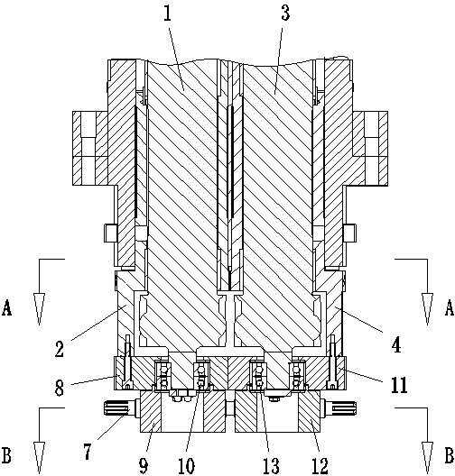
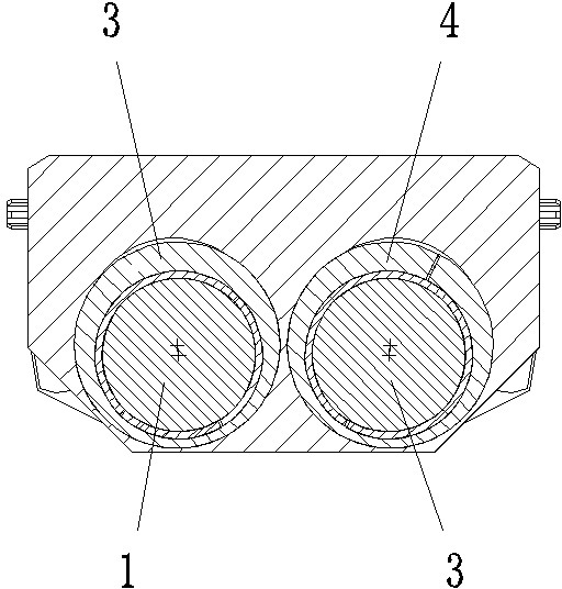
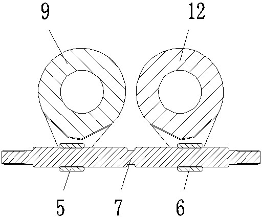
[0013] figure 1 It is a structural schematic diagram of a roll gap adjustment mechanism of the present invention; figure 2 for figure 1 Sectional view along A-A; image 3 for figure 1 Sectional view along B-B; Figure 4 for figure 1 bottom view.

[0014] The roll gap adjustment mechanism in this embodiment includes a first roll shaft 1, a first sleeve 2 that is overlaid on the first roll shaft 1 and is eccentric to it, a second roll shaft 3, and a first sleeve that is overlaid on the second roll shaft 3 and is eccentric to it. Two axle sleeves 4, also comprise the first nut 5, the second nut 6 and the leading screw 7 that is screwed with the first nut 5, the second nut 6 simultaneously, the screw thread that cooperates with the first nut 5 on the described leading screw 7 and The two screw threads that cooperate with the second nut 6 are in opposite directions; the first nut 5 is hinged with the first transmission member that is fixedly fitted with the first sleeve 2, a...


PUM


Abstract

The invention discloses a roll gap regulating mechanism. The roll gap regulating mechanism comprises a first roll shaft, a first shaft sleeve, a second roll shaft and a second shaft sleeve, and also comprises a first nut, a second nut and a screw which is in threaded fit with the first nut and the second nut at the same time; on the screw, threads matched with the first nut have opposite screwing directions with threads matched with the second nut; the first nut is hinged with the first shaft sleeve, or the first nut is hinged with a first transmission component which is fixedly matched with the first shaft sleeve; and the second nut is hinged with the second shaft sleeve, or the second nut and a second transmission component which is fixedly matched with the second shaft sleeve. In the roll gap regulating mechanism, the screw is arranged on the nuts, so that the mass of a box body is relatively light; the two nuts on the screw can move to the two ends or the middle part of the screw symmetrically and equidistantly by rotating the screw, and the screw drives the shaft sleeves to rotate so as to symmetrically regulate roll gaps of two rolls, so that the regulation is convenient; and the first nut and the second nut bear equal loads, so that the bearing performance is higher and the roll gap regulating mechanism has a longer service life.

Description

technical field [0001] The invention relates to a rolling mill, in particular to a roll gap adjustment mechanism of the rolling mill. Background technique [0002] The roll box of the cantilever rolling mill has a small space structure and a small distance between the centers of the roll shafts. Generally, the roll shaft is installed in the eccentric sleeve of the roll box body, and the screw nut is used to rotate the eccentric sleeve to symmetrically adjust the roll gap distance. The nut in the lever nut adjusting mechanism is hingedly connected with the eccentric sleeve. Due to the small structural size of the roller box, when adjusting the eccentric sleeve, while the nut moves axially on the screw rod, the position of the hinge point of the nut driving the eccentric sleeve also changes. To overcome this problem, the common method is to move the screw The position of the rod is fixed, and a connecting plate is added between the nut and the eccentric sleeve, and the rotati...

Claims


Application Information

Patent Timeline
IPC IPC(8): B21B31/24B21B37/58
Inventor 陈莹卷陈义杨虎成李图学
Owner CISDI ENG CO LTD
Why Eureka
Try Eureka