Boring cutter rod error compensating device with slide block structure

An error compensation and boring bar technology, which is applied in the field of boring bar error compensation devices, can solve the problems of low precision of the compensation device and small compensation range, and achieve the effects of realizing tool wear compensation, reducing error repetition and improving cylindricity

Inactive Publication Date: 2012-09-19
JIANGSU GAOJING MECHANICAL & ELECTRICAL EQUIPMENT CO LTD
View PDF7 Cites 6 Cited by
  • Summary
  • Abstract
  • Description
  • Claims
  • Application Information

AI Technical Summary

Problems solved by technology

[0004] The purpose of the present invention is to provide a boring tool bar error compensation device with a slider structure, which can accurately and continuously realize the micro-feeding of the fine boring tool in the alternating positive and negative directions through the slider, and solve the problem of low precision and compensation of existing compensation devices. Too small a problem

Method used


Image

  • Boring cutter rod error compensating device with slide block structure
  • Boring cutter rod error compensating device with slide block structure
  • Boring cutter rod error compensating device with slide block structure

Examples


Embodiment Construction

[0016] The present invention will be described in further detail below in conjunction with the accompanying drawings.

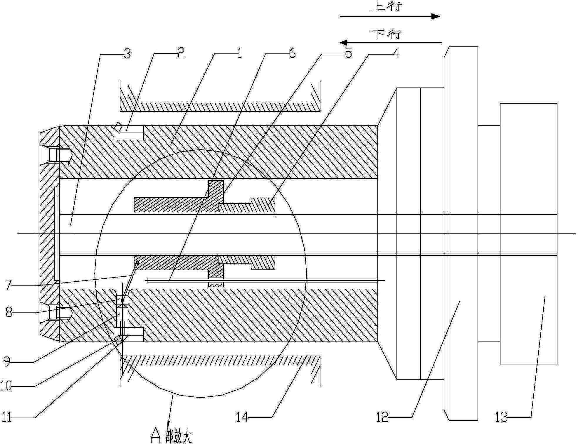
[0017] Such as figure 1 As shown, the boring tool bar error compensation device with a slider structure of the present invention includes a tool compensation servo motor 13, a power head and a spindle box 12, and a boring tool bar 1 with a slider structure.

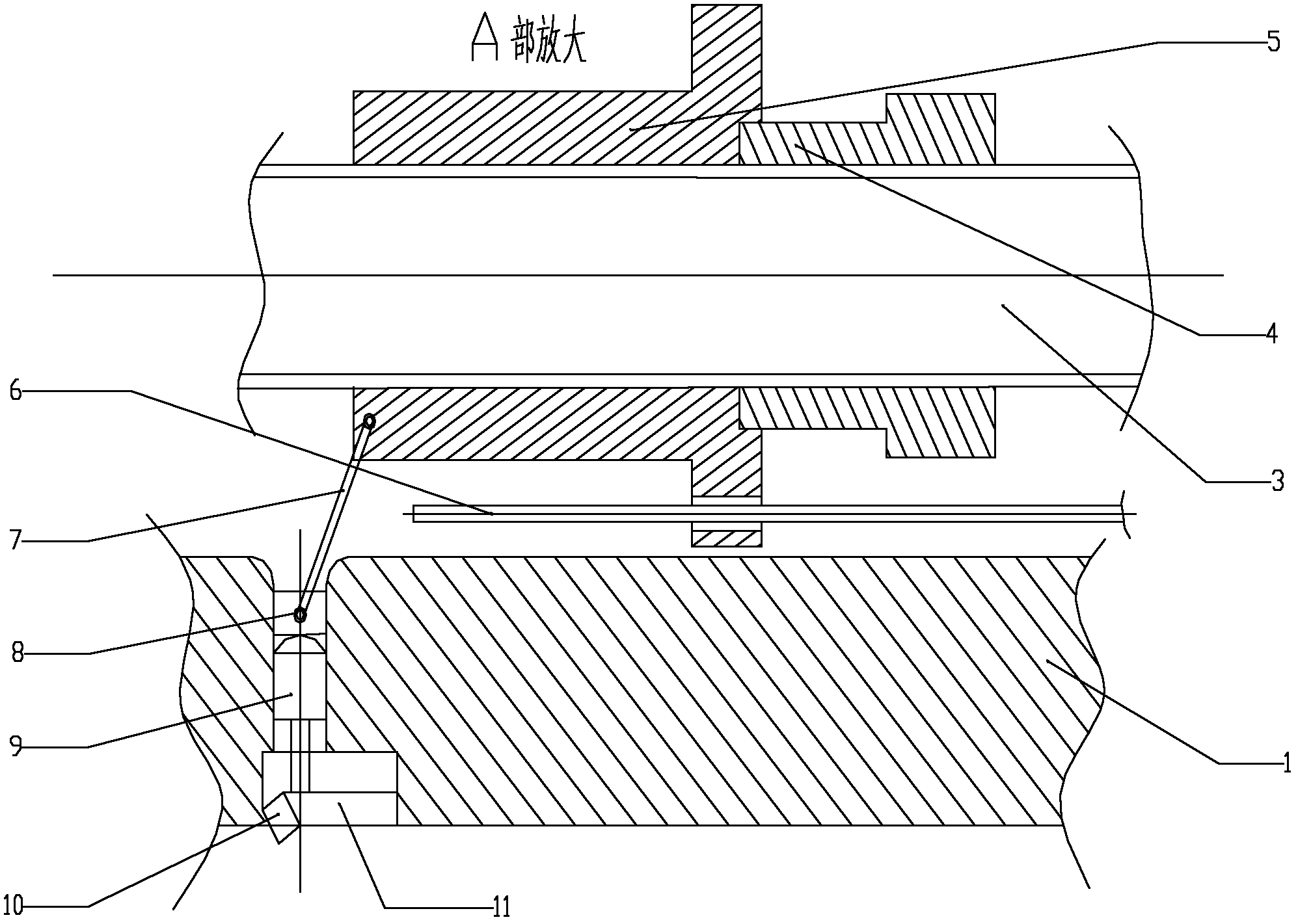
[0018] Such as figure 2 As shown, the boring bar 1 includes a semi-fine boring blade 2, a ball screw 3, a feed nut 4, a nut sleeve 5, a guide rod 6, a connecting rod 7, a slider 8, a ball stud 9, a fine boring blade 10 and Fine boring tool table 11.

[0019] There is a through hole in the center of the boring bar 1, and one end of the ball screw 3 extends into the center through hole, and the other end is directly connected with the tool compensation servo motor 13. The ball screw 3 is sleeved with a long cylindrical feed nut 4 matching it, the feed nut 4 is consolidated with the nut sleeve 5, and th...


PUM


Abstract

The invention discloses a boring cutter rod error compensating device with a slide block structure. The boring cutter rod error compensating device comprises a boring cutter rod and a cutter compensation servo motor, wherein the boring cutter rod is provided with an axial central hole; one end of a ball screw is connected with an output shaft of the cutter compensation servo motor; the other end of the ball screw stretches into the central hole; a screw nut assembly which can move relatively is sleeved on the ball screw; the ball screw drives the screw nut assembly to move in a straight line relatively; a connecting rod is connected with the screw nut assembly; a slide block is connected with one end of the connecting rod far away from the screw nut assembly; a straight hole slide groove is arranged on the side wall of the boring cutter rod; the slide block is arranged in the straight hole slide groove and can be driven by the connecting rod to slide in the straight hole slide groove; a ball pin is arranged in the straight hole slide groove; one end of the ball pin props against the slide block through an end part ball; and the other end of the ball pin is connected with the boring cutter on the side wall of the boring cutter rod. With the boring cutter rod error compensating device, rough and finish machining can be accomplished for one time; the abrasion of the fine boring cutter is reduced; and precise compensation to the cutter abrasion and the cylinder hole cylindrical form error is realized.

Description

technical field [0001] The invention belongs to the technical field of boring pin processing, and in particular relates to a boring bar error compensation device, which is suitable for error compensation in fine boring technology. Background technique [0002] The cylinder block is one of the key components in the engine, and its processing quality will directly affect the performance of the engine. Fine boring cylinder bore is one of the key processes in automobile engine production. In fine boring machining, the hole diameter error caused by tool wear, thermal deformation and other reasons is an important factor affecting the hole diameter error. The conventional boring method is to pull boring first and then push boring or push boring first and then pull boring. The shape of the processed cylinder hole must be waist-drum shape, so that the cylindricity of the bored hole is not high. [0003] The existing boring bar error compensation device generally adopts the inclined...

Claims


Application Information

Patent Timeline
Patent Type & Authority Applications(China)
IPC IPC(8): B23Q15/16B23Q11/00B23B47/00
Inventor 沈大为邵新宇郑金来喻道远徐秀兵李培根童双喜乐胜年李金友龚文明
Owner JIANGSU GAOJING MECHANICAL & ELECTRICAL EQUIPMENT CO LTD
Why Eureka
Try Eureka