Clamping force setting method and device of injection molding machine

A technology of injection molding machine and setting method, which is applied in the field of mold clamping force setting and mold clamping force setting device of injection molding machine, can solve the problem of difficulty in finding the minimum mold clamping force, trouble, and difficulty in finding the correct value And other issues

Active Publication Date: 2012-09-19
FANUC LTD
View PDF4 Cites 6 Cited by
  • Summary
  • Abstract
  • Description
  • Claims
  • Application Information

AI Technical Summary

Problems solved by technology

However, in the technology disclosed in this patent document, coefficients such as the projected area and safety factor need to be calculated, and it is necessary to analyze the metal mold screen to obtain the projected area, which is very troublesome.
In addition, since the safety ratio to be obtained is generally an empirical value, it is extremely difficult to obtain an accurate value.
Therefore, it is difficult to find the correct minimum clamping force with this technique

Method used


Image

  • Clamping force setting method and device of injection molding machine
  • Clamping force setting method and device of injection molding machine
  • Clamping force setting method and device of injection molding machine

Examples


Embodiment Construction

[0032] Figure 4 It is a side view of an injection molding machine capable of setting mold clamping force using the mold clamping force setting method of the present invention.

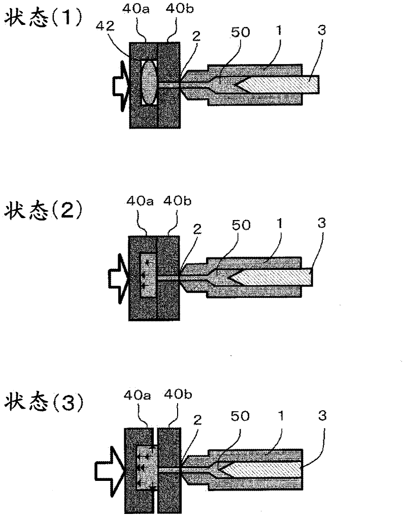
[0033] The injection molding machine M has a mold clamping unit Mc and an injection unit Mi on a machine base (not shown). The injection part Mi heats and melts the resin material (pellet) and injects the molten resin into the cavity of the mold 40 . The mold clamping part Mc mainly performs opening and closing of the mold 40 (the movable side mold 40a and the fixed side mold 40b).

[0034] First, the injection site Mi will be described. A nozzle 2 is attached to the front end of an injection cylinder 1 , and a screw 3 is passed through the injection cylinder 1 . A resin pressure sensor 5 is provided on the screw 3 , and a load cell or the like that detects the pressure of the resin by the pressure applied to the screw 3 is used. The output signal of the resin pressure sensor 5 is converted into a...


PUM


Abstract

According to a first preset clamping force (Fs1) closed metal mold, a molten resin is injected into the metal mold and the maximum value (Fmax1) in the real clamping force detected during the molten resin injection process is used as a first maximum detected clamping force to be taken out. A second maximum detected clamping force (Fmax 2) is taken out by performing the above same action according to a second preset clamping force (Fs2). A point (Fs1, Fmax1) and a point (Fs2,Fmax2) are labeled on a coordinate, wherein the preset clamping force is used as horizontal axis and the maximum detected clamping force is used as longitudinal axis; and the two points are connected by straight line. The value of the preset clamping force on the cross point of the straight line and the straight line for representing the maximum detected clamping force and the preset clamping force is used as the proper clamping force to be used.

Description

technical field [0001] The present invention relates to a mold clamping force setting method and a mold clamping force for obtaining an appropriate mold clamping force that does not generate flash and deform the metal mold from the resin pressure generated when the resin is injected into the mold in an injection molding machine Set up the device. Background technique [0002] When the molten resin is injected into the mold, if the mold clamping force against the molten resin is insufficient, the mold may open and flash may occur. On the other hand, if the mold clamping force is too large, there is no need to worry about flashing, but there will be problems such as mold deformation, molded product dimensions outside the specified value, or mold life shortening. Therefore, it is desirable to set the mold clamping force to an appropriate value that does not cause flash and deforms the mold. [0003] In the case of insufficient clamping force, use figure 1 as well as figure...

Claims


Application Information

Patent Timeline
Patent Type & Authority Applications(China)
IPC IPC(8): B29C45/64B29C45/76
CPCB29C2945/76936B29C2945/76505B29C2945/76224B29C2945/76869B29C2945/76391B29C45/7653B29C2945/76013B29C2945/76702
Inventor 中尾晴彦内山辰宏
Owner FANUC LTD
Why Eureka
Try Eureka