Device for controlling temperatures of pole sole of magnetic track brake and track as well as control method thereof

A technology of temperature control device and magnetic rail brake, which is applied in the direction of brake, brake safety system, railway brake system, etc. where the braking element interacts with the track, can solve the problems of increased wear and easy rise, and achieve improved adhesion. , prolong the service life, reduce excessive wear and the effect of stick welding

Active Publication Date: 2012-09-19
江苏大学扬州(江都)新能源汽车产业研究所
View PDF8 Cites 5 Cited by
  • Summary
  • Abstract
  • Description
  • Claims
  • Application Information

AI Technical Summary

Problems solved by technology

[0004] The purpose of the present invention is to overcome the defect that the temperature of the pole shoe and the rail is easily increased during the working process of the current magnetic rail brake, resulting in aggravated wear, and to provide a pole shoe and rail temperature control device and control method with simple structure and reliable performance. During the braking process of the magnetic track brake, the high temperature generated by the pole shoe and the track due to frictional braking can be reduced, the occurrence of sticking welding can be reduced, and the safety of the excitation coil of the electromagnetic track brake can be improved.

Method used


Image

  • Device for controlling temperatures of pole sole of magnetic track brake and track as well as control method thereof
  • Device for controlling temperatures of pole sole of magnetic track brake and track as well as control method thereof

Examples


Embodiment Construction

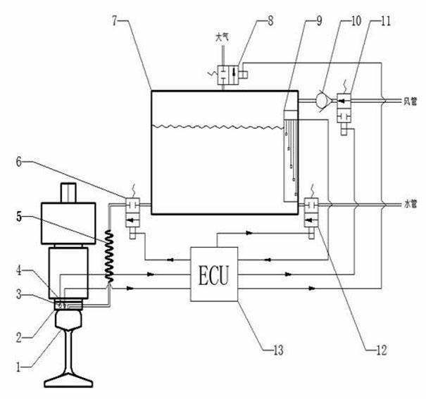
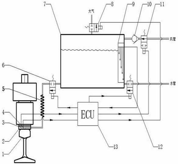
[0015] Such as figure 1 As shown, a control device for magnetic rail brake pole shoes and track temperature of the present invention includes an electronic control unit 13 and first and second non-contact temperature sensors 3 and 4 connected to the electronic control unit 13 through signal lines, wherein, The first non-contact temperature sensor 3 detects the temperature of the brake pole shoe 2 , and the second non-contact temperature sensor 4 detects the temperature of the rail 1 .

[0016] There is a water hole on the side of the brake pole shoe 2, and a small water spray hole is opened on the bottom of the brake pole shoe 2. The water hole and the water spray hole are connected inside the brake pole shoe 2. The elastic hose 5 and the first solenoid valve 6 that is normally closed and powered on are connected to the lower part of the airtight water tank 7 . The cooling water in the water tank 7 enters by the side water holes of the brake pole shoe 2, and can spray water t...


PUM


Abstract

The invention discloses a device for controlling temperatures of a pole sole of a magnetic track brake and a track as well as a control method thereof. A first non-contact temperature sensor and a second non-contact temperature sensor are respectively used for detecting the temperature of the pole sole of the magnetic track brake and the steel track; a water through hole is formed in the side face of the pole sole of the magnetic track brake; small water spraying holes are formed at the bottom of the pole sole of the magnetic track brake; the water through hole and the small water spraying holes are communicated inside the pole sole of the magnetic track brake; the water through hole is connected with the lower part of a water tank in a sealed manner by passing through a spiral elastic hose and a first solenoid valve in sequence; a liquid meter is arranged in the water tank; the top of the water tank is communicated with atmosphere through a second solenoid valve; the side part of the water tank is connected with a water pipe connected on a train through a fourth solenoid valve; the side part of the water tank is sequentially connected with an air duct on the train through a one-way valve and a third solenoid valve in sequence; and the liquid meter and the solenoid valves are connected with an electronic control unit. The device provided by the invention can effectively cool the pole sole and the steel track, so that the excessive abrasion and the adhesive welding of the pole sole and the steel track can be prevented when the magnetic track brake works.

Description

technical field [0001] The invention relates to a magnetic rail brake pole shoe and rail temperature control device and a control method thereof, which belong to the technical field of rail vehicle braking technology. Background technique [0002] Magnetic track brakes are mainly composed of brake beams, suspension / lifting devices, magnets, pole shoes, etc. The working principle of the magnetic rail brake is to use the friction resistance generated when the brake pole shoe and the rail surface move relative to each other to decelerate, so as to achieve the purpose of braking. The braking process is a dynamic friction process. Its friction braking system is composed of pole shoes, rail surfaces and interface film. Friction converts the kinetic energy of the train into heat energy, and at the same time causes the temperature of the rail and pole shoes to increase and the wear to increase. . The high temperature generated during the friction process will have a huge impact on...

Claims


Application Information

Patent Timeline
Patent Type & Authority Applications(China)
IPC IPC(8): B61H7/08B60T17/22
Inventor 陈士安王胜何仁顾宇峰厉萱张世金姚明
Owner 江苏大学扬州(江都)新能源汽车产业研究所
Why Eureka
Try Eureka