Small multi-purpose crane
A crane and multi-purpose technology, applied in the direction of cranes, etc., can solve the problems that it is not suitable for lifting and handling medium and small items, the turning radius of the boom is large, and it is not suitable for indoor use, etc., and achieves light weight, fast drying of clothes, and good ventilation Effect
- Summary
- Abstract
- Description
- Claims
- Application Information
AI Technical Summary
Problems solved by technology
Method used
Image
Examples
Embodiment 1
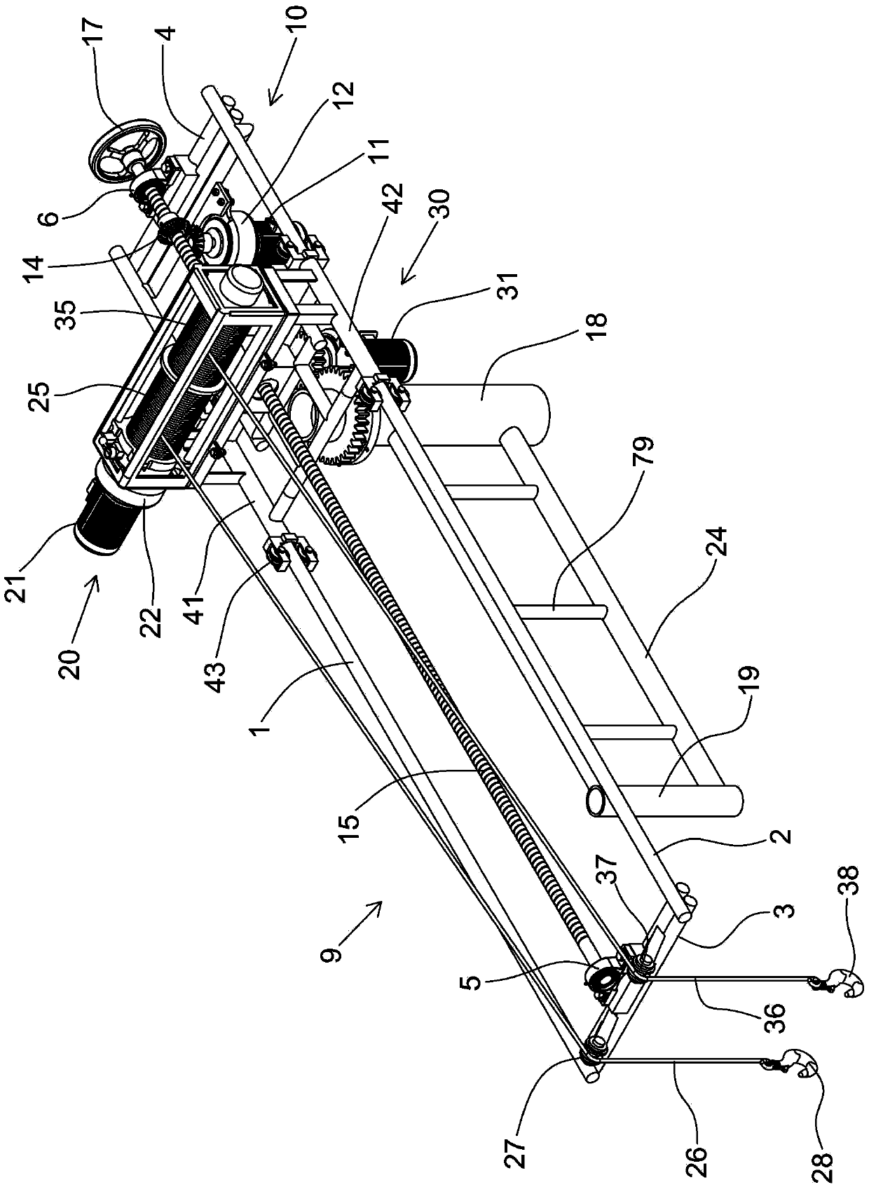
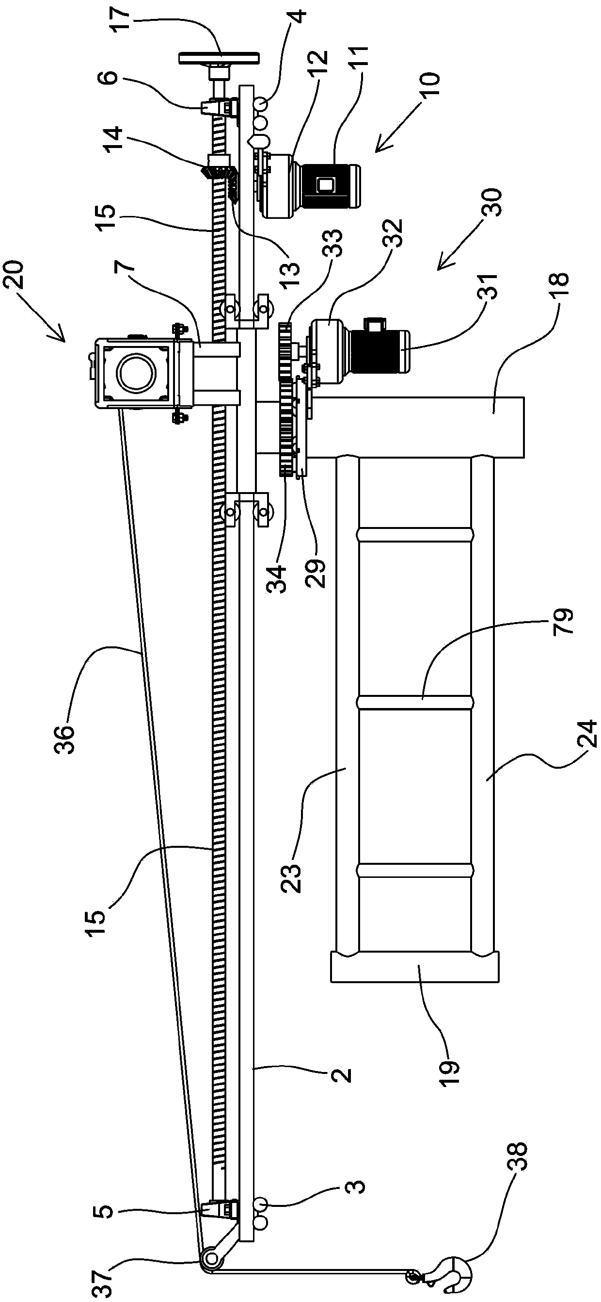
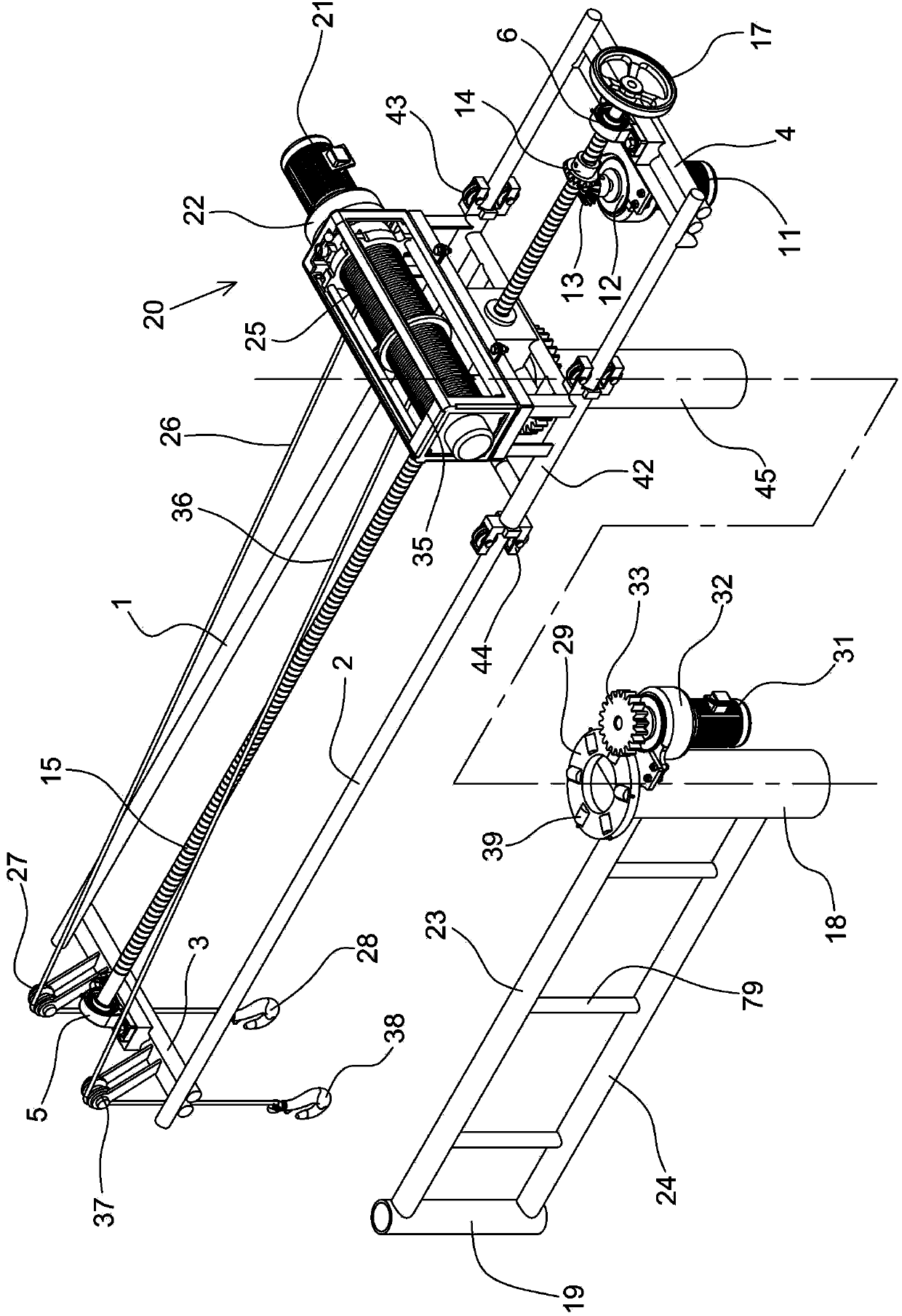
[0064] Please refer to figure 1 , figure 2 , image 3 , Figure 4 , Figure 5 , the present invention is a kind of multi-purpose small-sized crane, comprises boom 9, telescopic drive device 10, lifting drive device 20, rotary drive device 30, swivel frame 40 and sleeve 18, and boom 9 is made of a pair of parallel slide bar 1 . Figure 4 , the rotating frame 40 is a square frame welded by steel pipes, the top of the rotating frame 40 is provided with a platform 7, the platform 7 is welded by angle iron, the two sides of the rotating frame 40 are provided with slideways 41, 42, and the slideways 41 , 42 are made of thick steel pipes, rollers 43 are installed at the front and rear ports of the slideway 41, rollers 44 are installed at the front and rear ports of the slideway 42, and the sliding bars 1 and 2 of the boom are set on the sides of the rotating frame. In slideway 41,42, sliding bar 1,2 and roller 43,44 at slideway port place are in sliding fit, and the bottom of r...
Embodiment 2
[0073] Please refer to Figure 10 , Figure 11 , Figure 12 , Figure 13 , Figure 14 , in this embodiment, the crane is installed on the movable support 50. The support 50 is composed of No. 1 ladder 51, No. 2 ladder 52, and No. 3 ladder 53. No. 1 ladder 51 and No. 2 ladder 52 are supported in a herringbone shape. The upper ends of No. 1 ladder 51 and No. 2 ladder 52 are hinged by hinge shafts 54 Together, the lower ends of the No. 1 ladder 51 and the No. 2 ladder 52 are respectively fixed on the No. 3 ladder 53 through bolt fasteners 55, and the top of the No. 3 ladder 53 is welded with an ear plate 56 for piercing the bolt fastener 55. No. 1 ladder 51, No. 2 ladder 52, and No. 3 ladder 53 are supported in a triangle. In order to make the support 50 more firm, connecting plates 57, 58 are provided between the middle parts of No. 1 ladder 51 and No. 2 ladder 52. Plates 57 and 58 are fixed to No. 1 ladder 51 and No. 2 ladder 52 by bolt fasteners 88 . Ear plates 89 for pie...
Embodiment 3
[0077] Please refer to Figure 16 , Figure 17 , the present embodiment is a vehicle-mounted installation, the crane is installed on the bracket, and the bracket is composed of No. 1 ladder 51. Two sleeves 61, 71 are installed on No. 1 ladder 51. The installation method is the same as that of the above-mentioned embodiment. No. 1 ladder 51 Installed on the automobile 77 by clips or U-shaped bolts 76, it becomes a truck-mounted crane. Handling efficiency, reduce the labor intensity of porters, and easy installation, when it is necessary to lift, it can be quickly installed on the car 77 through clips or U-shaped bolts 76, and can be easily removed from the car 77 when it is not necessary to lift. Occupies the cargo space of the vehicle.
PUM
 Abstract
Description
Claims
Application Information
 - R&D
- Intellectual Property
- Life Sciences
- Materials
- Tech Scout
- Unparalleled Data Quality
- Higher Quality Content
- 60% Fewer Hallucinations
Browse by: Latest US Patents, China's latest patents, Technical Efficacy Thesaurus, Application Domain, Technology Topic, Popular Technical Reports.
© 2025 PatSnap. All rights reserved.Legal|Privacy policy|Modern Slavery Act Transparency Statement|Sitemap|About US| Contact US: help@patsnap.com


