Stations of open-end rotor spinning machines

A technology of rotor spinning and free end, which is applied in the direction of free end spinning machine, spinning machine, continuous winding spinning machine, etc. It can solve the problems of long positioning duration, adverse effects of power consumption, and hindrance of cross-winding bobbin changeover. Canister cleaning and other issues, to achieve the effect of low structural cost

Active Publication Date: 2016-02-17
SAURER GERMANY GMBH & CO KG
View PDF8 Cites 0 Cited by
  • Summary
  • Abstract
  • Description
  • Claims
  • Application Information

AI Technical Summary

Problems solved by technology

[0010] However, the problem with such self-sufficient stations is that the suction nozzle, when its drive is switched off, falls under the force of gravity to a lower position where it interferes with the cross-winding bobbin changer Clean critical areas of the workplace in the prescribed manner
[0011] Although the power consumption is low during the electronic positioning of the nozzles, this has a detrimental effect due to the large number of nozzles combined with the relatively long duration of the positioning
This means that the electronic positioning of the suction nozzles during the weaving process has a negative impact on the operating costs of such open-end rotor spinning machines

Method used


Image

  • Stations of open-end rotor spinning machines
  • Stations of open-end rotor spinning machines
  • Stations of open-end rotor spinning machines

Examples


Embodiment Construction

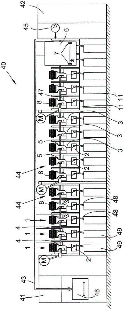
[0025] figure 1 A front view is shown schematically of an open-end rotor spinning machine 40 with end frames 41 , 42 and a plurality of self-contained workstations 1 of the same type arranged between the end frames 41 , 42 .

[0026] As usual, the textile machine's own vacuum source 45 , the power supply and the central control unit 46 of the free-end rotor spinning machine 40 are provided, for example, on the end frame 41 or 42 . The central control unit 46 itself is preferably connected via a bus system 43 to a workstation computer 47 of the individual workstations 1 .

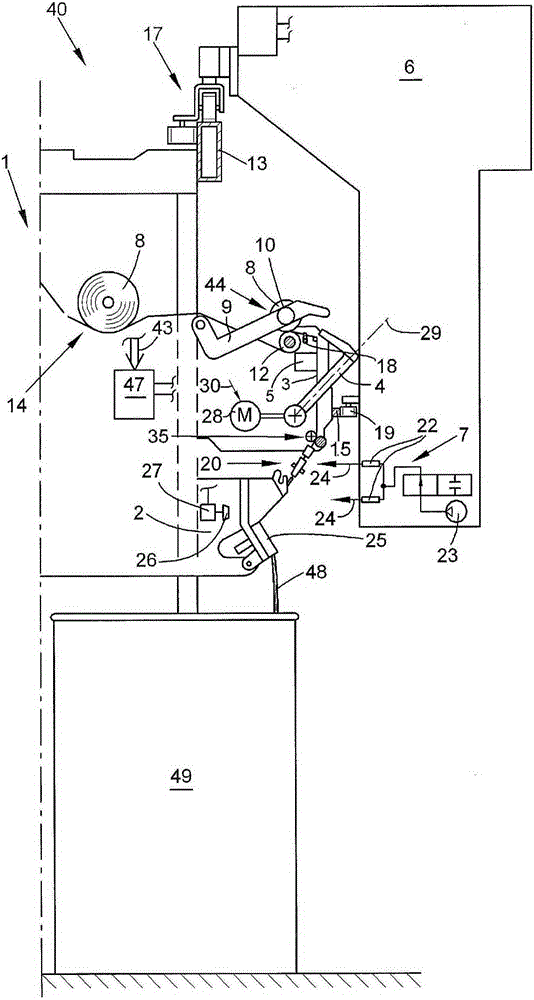
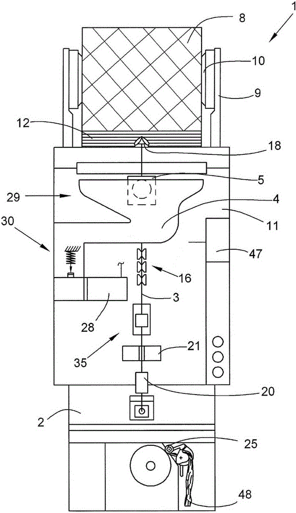
[0027] A large number of stations 1 each have a station housing 11 containing an open-end spinning device 2 , a winding device 44 , a suction nozzle 4 and other known yarn treatment devices, such as a waxing device 5 . On station 1, by means of the free-end spinning device 2, the feed fiber sliver 48 stored in the spinning barrel 49 (which is arranged side by side below the station 1) is spun into a yarn 3,...


PUM


Abstract

The workstation (1) has an open-end spinning device (2) for producing a thread, and a winding device for producing a cross coil. A suction nozzle (4) is pivotably mounted and motor-driven for pneumatic reception of thread ends accumulated on the cross coil. A locking device (30) locks the suction nozzle in a predetermined rest position (29). The locking device is arranged in a region of a pivot axis of the suction nozzle. The locking device is formed as a mechanical operating device, which reliably fixes the suction nozzle when a stepper motor (28) is switched off.

Description

technical field [0001] The invention relates to a working station of an open-end rotor spinning machine. Background technique [0002] Open-end rotor spinning machines have been disclosed in various embodiments and described in detail in numerous patent applications. Open-end rotor spinning machines of this type usually have a large number of stations of the same type arranged side by side, at which a yarn is spun from a fiber sliver, for example stored in a spinning drum, and the yarn is subsequently wound into a cross-wrap Around the bobbin. For this purpose, the stations of such an open-end rotor spinning machine in particular each have an open-end spinning device for producing the yarn and a winding device for producing the cross-wound bobbins. [0003] With regard to their other embodiments and the mode of operation associated therewith, the workstations of these open-end rotor spinning machines still differ significantly, especially in the event of a yarn break. [...

Claims


Application Information

Patent Timeline
Patent Type & Authority Patents(China)
IPC IPC(8): D01H4/48
Inventor 海因茨-迪特尔·戈培尔海因茨-约瑟夫·波伊克
Owner SAURER GERMANY GMBH & CO KG
Why Eureka
Try Eureka