Adaptive photoelectric electronic yarn cleaner

An electronic yarn clearer, optoelectronic technology, applied in the field of textile machinery control and embedded systems, can solve the problems of complex settings, yarn detection failures, and low detection accuracy.

Active Publication Date: 2012-09-19
HANGZHOU DIANZI UNIV
View PDF9 Cites 11 Cited by
  • Summary
  • Abstract
  • Description
  • Claims
  • Application Information

AI Technical Summary

Problems solved by technology

[0004] The invention is aimed at the yarn detection failure caused by the aging of the

Method used


Image

  • Adaptive photoelectric electronic yarn cleaner
  • Adaptive photoelectric electronic yarn cleaner
  • Adaptive photoelectric electronic yarn cleaner

Examples


Embodiment Construction

[0033] The present invention will be further described below in conjunction with accompanying drawing.

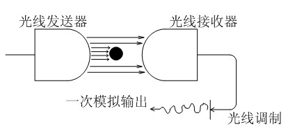
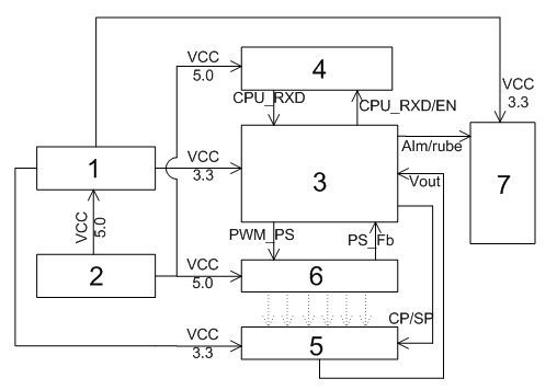
[0034] Specific embodiments of the present invention are shown in the accompanying drawings, figure 1 Shown is the basic principle of optical yarn detection, the yarn to be detected is moved in the area between the light transmitter (LED external light source) and the light receiver (photoelectric sensor), so that the change of the yarn diameter can be Determined by the change in luminous flux received on the light receiver. figure 2 Shown is a schematic block diagram of the structure of the yarn detection circuit, which is mainly composed of the first power module 1, the second power module 2, the control module 3, the RS485 communication module 4, the signal detection module 5, the external light source module 6, and the alarm display operation module Composed of 7.

[0035] The working process of the electronic yarn clearer is as follows: when the yarn passes between ...


PUM


Abstract

The invention relates to an adaptive photoelectric electronic yarn cleaner, which comprises a power supply management module, a control module, an RS485 communication module, a signal detection and interface module, an external light source module and an alarm display and operation module. The control module is used for giving a voltage value required for driving the external light source module, converting the highest analog voltage value acquired and processed by a photoelectric sensor into a digital value through an internal analog-to-digital (A/D) module, comparing the value with a system set brightness value to judge whether the current brightness value is compliant with the set value or not, and accordingly and properly adjusting the duty ratio of the output pulse width modulation (PWM) square waves to adjust the voltage value of the light source module. The adaptive photoelectric electronic yarn cleaner has the advantages that the acquisition accuracy is further improved and an alarm display circuit on the periphery of a chip can provide more intuitive information for operators.

Description

technical field [0001] The invention belongs to the technical field of embedded systems, relates to a yarn detection head in the field of textile machinery control, in particular to a sensing circuit based on AD sampling and a detection control circuit of a single-chip microcomputer core. Background technique [0002] Affected by many factors during the yarn forming process, yarn defects often occur, whether it is traditional spinning methods or various new spinning methods (rotor spinning, air-jet spinning, etc.), even if the best Spinning raw materials, the latest spinning equipment and the best spinning process, yarn defects are also inevitable. The occurrence of yarn defects seriously affects the quality of yarn and cloth surface. To improve product quality and increase economic benefits, one of the main tasks of textile mills is to effectively control yarn defects and maintain stable yarn uniformity on the basis of improving production efficiency, so as to weave high-q...

Claims


Application Information

Patent Timeline
IPC IPC(8): D01H13/32G01N21/88
Inventor 赵晓东贾孔昊邹洪波孔亚广薛安克
Owner HANGZHOU DIANZI UNIV
Why Eureka
Try Eureka