Dynamic compactor for subgrade

A powerful compaction and roadbed technology, applied in roads, roads, buildings, etc., can solve problems such as poor effect of stabilizing the roadbed, labor-intensive time-consuming, low efficiency, damaged bridge body, etc., to achieve large force, avoid settlement, and high efficiency.

Active Publication Date: 2012-09-19
李祥莹
View PDF6 Cites 5 Cited by
  • Summary
  • Abstract
  • Description
  • Claims
  • Application Information

AI Technical Summary

Problems solved by technology

[0003] In order to solve the technical problems in the prior art that road rollers are poor in stabilizing the roadbed, labor-intensive and time-consuming, and have low efficiency, the present invention designs a roadbed powerful compaction machine, which realizes continuous and strong vibration of the roadbed through the vibration of the vibratory hammer, and achieves the resonance efficiency of soil particles , using the principle of resonance to apply strong compaction work to the soil foundation in the state of soil particles floating and sliding, to achieve rapid stability of the roadbed; at the same time, the force of the vibratory hammer mechanism is evenly dispersed by acting on the pressure equalizing convex strip in the middle of the bottom of the bottom plate, and at the same time Cut off the lateral pressure of the vibratory hammer mechanism on the soil through the arc-shaped grooves at the edge, so as to avoid excessive lateral pressure on the edge of the bridge, thereby damaging the bridge body

Method used


Image

  • Dynamic compactor for subgrade
  • Dynamic compactor for subgrade
  • Dynamic compactor for subgrade

Examples


Embodiment Construction

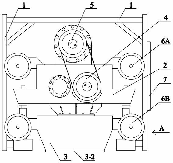
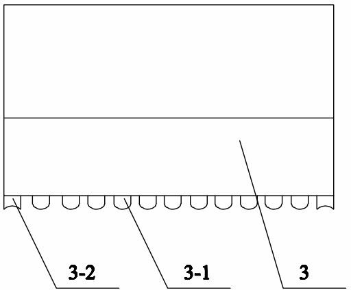
[0010] see figure 1 , a roadbed strong compactor, the structure includes a vibratory hammer mechanism with a vibratory hammer 2, a drive motor 5 and a vibrator 4, the key point is: at the bottom of the vibratory hammer 2, a number of convex strips are evenly distributed on the bottom surface Bottom plate 3, the convex strip structure includes two types: the side pressure breaking plate 3-2 arranged at the edge of the bottom surface of the action bottom plate 3 and the action surface is a concave arc surface, and evenly distributed in the middle of the bottom surface of the action bottom plate 3 And the acting surface is an equalizing convex strip 3-1 with a convex arc surface, and the lateral pressure breaking plate 3-2 cuts off the lateral pressure generated by the vibratory hammer 2 on the soil.

[0011] The above-mentioned protrusions are arranged along the longitudinal or transverse direction of the active bottom plate 3 .

[0012] The structure of the above-mentioned tam...


PUM


Abstract

The invention relates to a dynamic compactor for a subgrade. The dynamic compactor for the subgrade solves the technical problems of poor subgrade stabilizing effect, time consuming, labor consuming and low efficiency of a road roller in the prior art. The technical scheme is that dynamic compactor structurally comprises a vibratory hammer mechanism with a vibratory hammer, a driving motor and a vibration exciter, an acting bottom plate with evenly distributed ribs on the bottom surface is additionally arranged at the bottom end of the vibratory hammer and the ribs comprise two types, i.e. side pressing cutting-off plates and even pressing ribs, wherein the side pressing cutting-off plates are arranged on the edge of the bottom surface of the acting bottom plate and are respectively provided with an acting surface which is an inwards concave arc surface, the even pressing ribs are evenly distributed at the middle part of the bottom surface of the acting bottom plate and are respectively provided with an acting surface which is outwards convex arc surface, and the side pressing cutting-off plates can cut off external side pressure produced by the vibratory hammer to a soil body. The acting force of the vibratory hammer mechanism can be evenly dispersed through the even pressing ribs in the middle of the bottom of the acting bottom plate, the side pressure of the vibratory hammer mechanism to the soil body can be cut off through the side pressing cutting-off plates on the edge, and the situation that a bridge body is damaged because the side pressure to the edge of a bridge is too large can be avoided.

Description

technical field [0001] The invention relates to a roadbed rapid stabilizing device, which belongs to the field of road construction equipment industry, in particular to a roadbed powerful tamping machine. Background technique [0002] In the road construction industry, the stability of the subgrade of new roads is a major control indicator. In the existing technology, road rollers are generally used to stabilize the subgrade by compacting or preloading, and settlement to achieve the stability of the subgrade, but the stabilization effect is always unsatisfactory, and the subgrade continues to appear. Deformation, there is a great potential safety hazard, especially for high-speed railways, the deformation of the roadbed will directly affect the overall stability of the high-speed railway. For high-fill subgrades and bad geology in expressways, dynamic compaction is generally used, which is labor-intensive and time-consuming and inefficient. Therefore be necessary to researc...

Claims


Application Information

Patent Timeline
Patent Type & Authority Applications(China)
IPC IPC(8): E01C3/04
Inventor 李来宾李祥莹
Owner 李祥莹
Why Eureka
Try Eureka