Supplying electrical power in hydrocarbon well installation

A technology of oil and gas wells and electric power, which is applied in the direction of circuits, electrical components, thermoelectric devices, etc., and can solve problems such as limiting the availability of additional electric power

Inactive Publication Date: 2012-09-19
VETCO GRAY CONTROLS
View PDF7 Cites 0 Cited by
  • Summary
  • Abstract
  • Description
  • Claims
  • Application Information

AI Technical Summary

Problems solved by technology

configuration that may limit the availability of additional electrical power should future modifications to subsea equipment be required

Method used


Image

  • Supplying electrical power in hydrocarbon well installation
  • Supplying electrical power in hydrocarbon well installation
  • Supplying electrical power in hydrocarbon well installation

Examples


Embodiment Construction

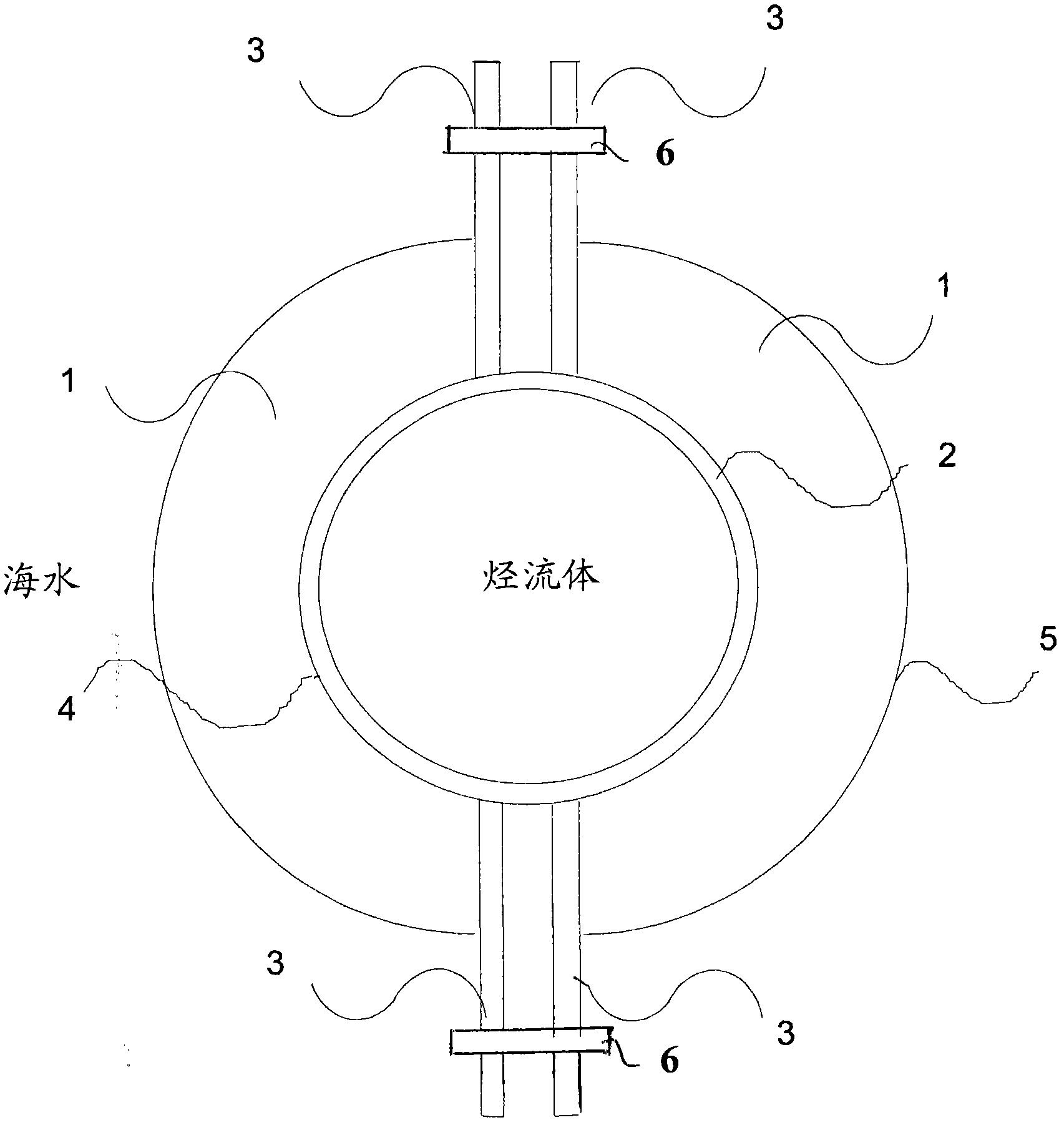
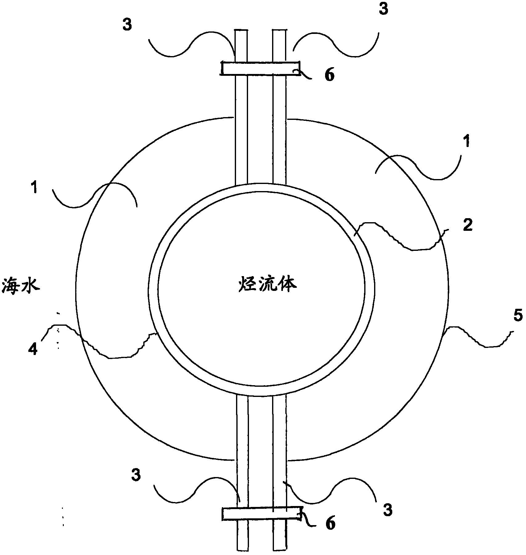
[0013] Embodiments of the invention take advantage of the temperature difference between the hot hydrocarbon fluid emerging in the subsea pipeline from an offshore well, which is typically about 70°C, and the seabed temperature outside the pipeline wall, which is typically about 5°C. Calculations show that this temperature gradient can be sufficient to generate more than 3 watts of DC electrical power when utilizing currently available thermoelectric modules mounted in a clamp configuration around the pipeline.

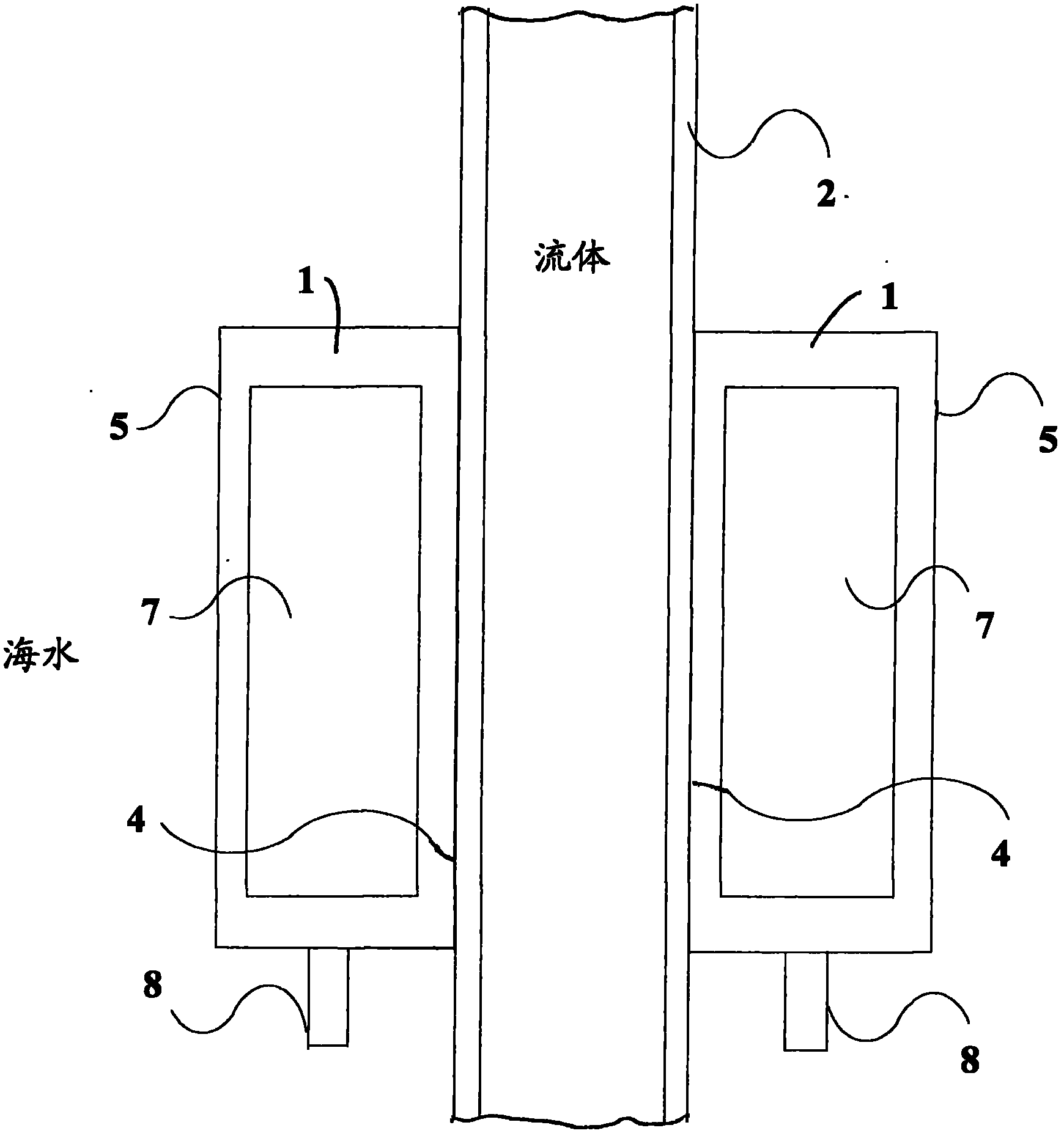
[0014] With reference to the drawings, thermoelectric generation is provided by integrating sufficient solid-state semiconductor-based thermoelectric modules into a fixture configuration comprising two roughly semicircular, C-shaped bodies 1, each forming a half-fixture around a fluid flow carrying hot hydrocarbon fluid Line 2 is assembled and clamped. Each C-shaped body 1 carries a flange 3 at each end, each flange 3 being fastened to a counter flange 3 of the other ...


PUM


Abstract

The invention relates to a method of providing electrical power in an underwater hydrocarbon well device. The underwater hydrocarbon well device has a pipeline (2) surrounded by water for conveying a hydrocarbon fluid, and the method comprises attaching at least one body (1) to the pipeline at its outside, the body carrying at least one thermoelectric generating device (7), so that the device is in a temperature gradient resulting from a difference in temperature between the hydrocarbon fluid and the water surrounding the pipeline. The body comprises a clamp body which is a part of a clamp arrangement clamped to the outside of the pipeline.

Description

technical field [0001] The present invention relates to the supply of electrical power in a subsea hydrocarbon well installation. Background technique [0002] In offshore oil production control systems, much of the control equipment is installed on the seabed. The subsea equipment, which primarily opens and closes the subsea valves that control and allow the flow of fluid from the well, must be highly reliable and operate in the harsh environment of the subsea surface and is required to operate satisfactorily over a lifetime of up to 25 years. Electric power for the equipment installed on the seabed is provided by an electric power unit mounted on it, for example on a drilling platform, a floating platform or on shore. [0003] The electrical power is carried to the subsea equipment via umbilical cables, which also include communication lines carrying control and instrument signals, and hydraulic lines carrying hydraulic fluid for electrically actuated hydraulic fluid cont...

Claims


Application Information

Patent Timeline
Patent Type & Authority Applications(China)
IPC IPC(8): E21B41/00
CPCE21B41/0007H01L35/30H01L35/00E21B41/0085Y10T29/49826H10N10/13
Inventor N·埃尔森
Owner VETCO GRAY CONTROLS
Why Eureka
Try Eureka