
Combustion chamber of high-speed diesel engine

A combustion chamber and diesel engine technology, which is applied in combustion engines, mechanical equipment, machines/engines, etc., can solve problems affecting the rationality and distribution of airflow movement organization, low air utilization rate, and fuel oil beam hitting the wall, etc., so as to promote Effect of atomization and space mixing and distribution, reduction of local combustion high temperature zone, and reduction of initial combustion rate

Inactive Publication Date: 2012-09-19
GUANGXI YUCHAI MASCH CO LTD
View PDF6 Cites 4 Cited by
  • Summary
  • Abstract
  • Description
  • Claims
  • Application Information

AI Technical Summary

Problems solved by technology

[0002] The combustion chamber of modern direct-injection diesel engines is generally an ω-shaped combustion chamber, which is composed of a combustion chamber throat, a hemispherical boss, and a combustion chamber arc. The combination of arcs and radians has limited effect on improving the combustion process, especially the high-speed diesel engine combustion chamber space is relatively small, the K coefficient of the combustion chamber is low, the air utilization rate is relatively low, the organization of the combustion process is more difficult, and the thermal efficiency will be relatively low
For high-pressure injection above 1400bar, there is still a serious phenomenon that the fuel beam hits the wall, and the shape of the combustion chamber affects the rationality of the airflow movement organization and the uniformity of the distribution of the mixture in the combustion chamber space, resulting in the utilization of air in the combustion chamber. Low efficiency, the combustion process cannot be fully carried out, resulting in poor engine emissions, high fuel consumption, and no further improvement in thermal efficiency

Method used


Image

  • Combustion chamber of high-speed diesel engine
  • Combustion chamber of high-speed diesel engine
  • Combustion chamber of high-speed diesel engine

Examples


Embodiment 1

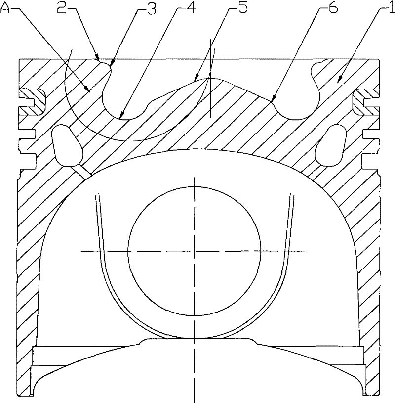
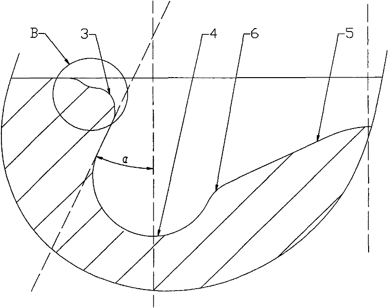
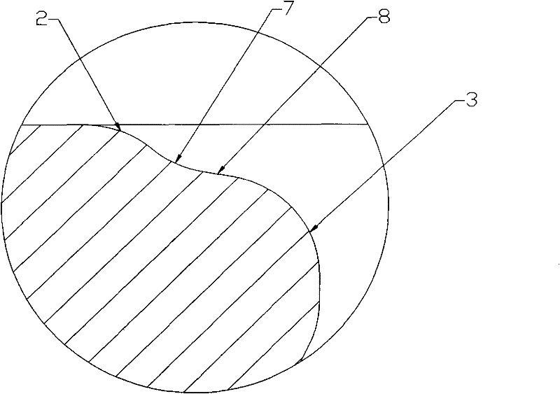
[0023] Figure 1 to Figure 4 Both are the content of Embodiment 1, figure 1 It is a schematic cross-sectional view of the combustion chamber of this embodiment. As shown in the figure, the cross-section of the combustion chamber is generally ω-shaped. 3. Bottom groove 4 and boss 5. The inner constriction 2 is an annular arc-shaped protrusion whose inner diameter decreases from the top of the piston rod 1. The mouth 3 is an annular arc-shaped protrusion transitionally connected to the bottom edge of the inner constriction 2, and its section is also a circular arc with the opening facing away from the central axis of the combustion chamber. The bottom groove 4 is an arc-shaped groove arranged on the bottom edge of the combustion chamber , the section of which is an opening facing the central axis of the combustion chamber and an arc towards the upper side. The boss 5 is a spherical crown structure arranged at the center of the bottom of the combustion chamber. The deflector 6,...

Embodiment 2

[0031] Compared with the first embodiment, the shape and function of this embodiment are the same as those of the first embodiment except that the specific dimensions are changed, so the structural connection relationship and working process will not be repeated here.

[0032] In this embodiment, the maximum inner diameter of the inner constriction 2 is 58.2 mm, the radius of the arc of the inner constriction 2 is 2 mm, the minimum inner diameter of the throat 3 is 49.1 mm, and the center of the arc of the throat 3 is aligned with the piston rod. The distance from the top of 1 is 2.5mm, the radius of the arc of the bottom groove 4 is 5.6mm, the distance from the center of the arc of the bottom groove 4 to the central axis of the combustion chamber is 20mm, and the center of the arc of the bottom groove 4 to the top of the piston rod 1 The distance between the tangent of the upper edge of the arc and the central axis of the combustion chamber is 20°, the radius of the boss 5 is ...


PUM


Abstract

The invention discloses a combustion chamber of a high-speed diesel engine. The combustion chamber is cylindrically arranged at the end part of a piston rod, and the combustion chamber is characterized in that the combustion chamber sequentially comprises an inward contraction port, a throat port, a bottom groove and a boss from the top end of the piston rod to the bottom of the combustion chamber, wherein the inward contraction port is of an annular arc-shaped groove with the inner diameter which is gradually reduced from the top end of the piston rod, the throat port is of an annular arc-shaped bulge connected to the bottom edge of the inward contraction port, the bottom groove is of an arc-shaped groove arranged on the edge at the bottom of the combustion chamber, the inner diameter of the throat port is smaller than those of the inward contraction port and the bottom groove, the boss is of a spherical crown-like structure arranged at the center of the bottom of the combustion chamber, a diversion table is arranged between the bottom edge of the boss and the lower edge of the bottom groove, and the diversion table is of an annular arc-shaped raised structure. The combustion chamber disclosed by the invention can be used for preventing a high-pressure injected oil beam from being subjected to a wall impingement phenomenon, improving the fuel oil spatial distribution and oil-gas mixing uniformity, and further ensuring that the engine is higher in thermal efficiency and lower uin oil consumption and emission.

Description

technical field [0001] The invention relates to the technical field of light-duty diesel engines, in particular to a combustion chamber of a high-speed direct-injection diesel engine. Background technique [0002] The combustion chamber of modern direct-injection diesel engines is generally an ω-shaped combustion chamber, which is composed of a combustion chamber throat, a hemispherical boss, and a combustion chamber arc. The combination of arcs and radians has limited effect on improving the combustion process, especially the high-speed diesel engine combustion chamber space is relatively small, the K coefficient of the combustion chamber is low, the air utilization rate is relatively low, the combustion process organization is more difficult, and the thermal efficiency will be relatively low. For high-pressure injection above 1400bar, there is still a serious phenomenon that the fuel beam hits the wall, and the shape of the combustion chamber affects the rationality of the...

Claims


Application Information

Patent Timeline
Patent Type & Authority Applications(China)
IPC IPC(8): F02B23/06
CPCY02T10/125Y02T10/12
Inventor 王辉李明星陈土润周健张锦
Owner GUANGXI YUCHAI MASCH CO LTD
Learn More