Floating plumbing body and flywheel plumbing arm self-energy generator

A floating vertical body and generator technology, applied in hydropower, engine components, machines/engines, etc., can solve the problems of multiple internal gear accessories, single-stage speed increase, etc.

Inactive Publication Date: 2012-09-19
朱永章
View PDF3 Cites 6 Cited by
  • Summary
  • Abstract
  • Description
  • Claims
  • Application Information

AI Technical Summary

Problems solved by technology

My utility model patent, patent number: ZL 200820016340.3 Bicycle center shaft speed-up device, there are many internal gear accessories, and it is a single-stage speed-up and other defects

Method used


Image

  • Floating plumbing body and flywheel plumbing arm self-energy generator
  • Floating plumbing body and flywheel plumbing arm self-energy generator
  • Floating plumbing body and flywheel plumbing arm self-energy generator

Examples


Embodiment Construction

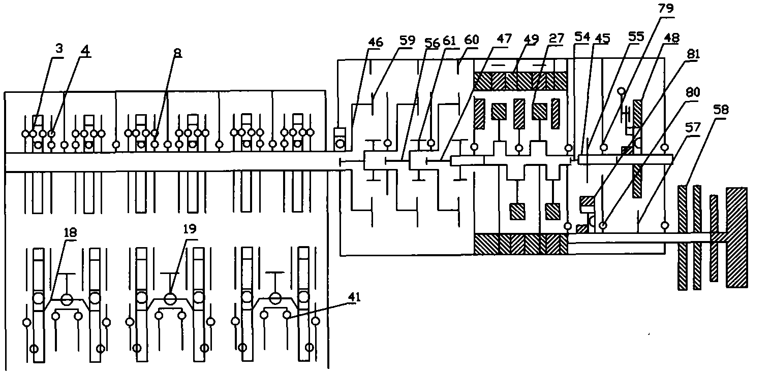
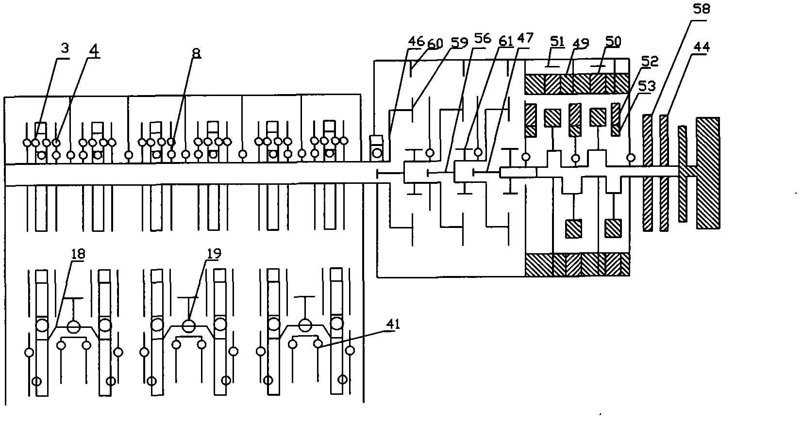
[0020] Multiple sets of large-diameter flywheel rings are installed on the long axis 2 of the elevated large-diameter flywheel ring. One set of large-diameter flywheel rings includes two large-diameter flywheel rings and two telescopic levers 43 below, namely the left telescopic lever and the right telescopic lever. , because the wire rope 18 in the middle of the front end of the left telescopic lever is slid by the upper sliding wheel 19, and the sliding wheels 41 on both sides of the fixed arc positioning groove are supported by the lower part, and the middle part of the front end of the left telescopic lever and the right telescopic lever is connected in the middle, because the wire rope 18 is in the middle of the front end of the right telescopic lever. The upper sliding wheel 19 has a small cross-load area, and the sliding wheels 41 on both sides of the fixed arc positioning groove must be installed below, so that the steel rope can pass through the sliding wheels 41 on bot...


PUM


Abstract

The invention relates to a floating plumbing body and flywheel plumbing arm self-energy generator. According to the floating plumbing body and flywheel plumbing arm self-energy generator, a plurality of groups of deepwater tanks and floating plumbing bodies alternatively push lever devices; a plurality of groups of wood floating plumbing bodies utilize buoyancy in each deepwater tank to reach above levers from the right parts below the levers and then utilize gliding inertance of the floating plumbing bodies to respectively achieve in a plurality of flywheel ring grooves; inclined gear rings in a plurality of flywheel rings alternatively fall in a free way on a long shaft movable tooth to drive a flywheel ring long shaft to continuously rotate downwards, so that the speed of a speed increaser is increased and lead the reinforcement is generated by an electromagnetic attraction machine; and when the long shaft rotates, generated nonuniform power drives a generator to run and generate electricity through a hammer throwing speed shifting mechanism. The generator provided by the invention belongs to the field of green electricity generation with no cost.

Description

technical field [0001] The floating pendant and flywheel pendant arm type self-energy generator belongs to the field of new energy and green power generation. Background technique [0002] Available in Bioenergy and Power Generation Technology / Edited by Yao Xingjia, etc.-Beijing: Science Press, 20101sbn 978-7-03-027952-1, China Edition Library c1p Data Hezi (2010) No. 115709, page 7 1.2.1 Solar power generation technology and its development overview. Solar thermal power generation converts solar radiation energy into thermal energy, and then converts thermal energy into electrical energy. It has two conversion forms, one is to directly convert the sun's thermal energy into electrical energy, and the other is to use the sun's thermal energy to drive a generator to generate electricity through a heat engine (such as a steam turbine). The latter is relatively mature in technology. At present, the world basically There are 5 forms of solar thermal power generation, namely trou...

Claims


Application Information

Patent Timeline
Patent Type & Authority Applications(China)
IPC IPC(8): F03B17/02H02K7/18
CPCY02E10/20
Inventor 朱永章
Owner 朱永章
Why Eureka
Try Eureka