Hand-operated reversing valve and sealing structure thereof

A manual reversing valve, sealing structure technology, applied in the direction of fluid pressure actuation device, servo motor assembly, mechanical equipment, etc., can solve the problems of poor anti-pollution ability, wear, indentation, etc., to improve service life and performance , strong anti-pollution ability, and the effect of reducing damage

Active Publication Date: 2012-09-19
益阳市科技成果转化服务中心 +1
View PDF8 Cites 3 Cited by
  • Summary
  • Abstract
  • Description
  • Claims
  • Application Information

AI Technical Summary

Problems solved by technology

However, the above-mentioned cone seal form is the main seal realized by the axial butt contact between the steel surface and the steel surface when the valve core moves in the axial direction. It has poor anti-pollution ability, and the pollution particles are easier to get stuck on the valve core and Between the sealing seats, resulting in the problem of poor sealing and liquid leakage of the valve core; the above-mentioned flat soft seal form is when the metal valve core moves in the axial direction, the ring end surface on the valve core and the rubber material seal. The main seal realized by the axial pressure contact of the flat end face, although the sealing effect is improved, but after the long-term reversing work of the manual reversing valve, the annular end face of the valve core will cause indentation and wear on the end face of the rubber seal In severe cases, the rubber seal may be worn out, affecting the service life and sealing effect of the rubber seal, and will eventually affect the service life of the manual reversing valve

Method used


Image

  • Hand-operated reversing valve and sealing structure thereof
  • Hand-operated reversing valve and sealing structure thereof
  • Hand-operated reversing valve and sealing structure thereof

Examples


Embodiment Construction

[0019] It should be noted that, in the case of no conflict, the embodiments in the present application and the features in the embodiments can be combined with each other. The present invention will be described in detail below with reference to the accompanying drawings and examples.

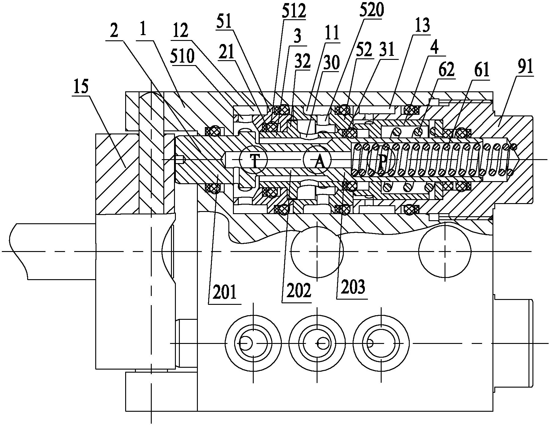
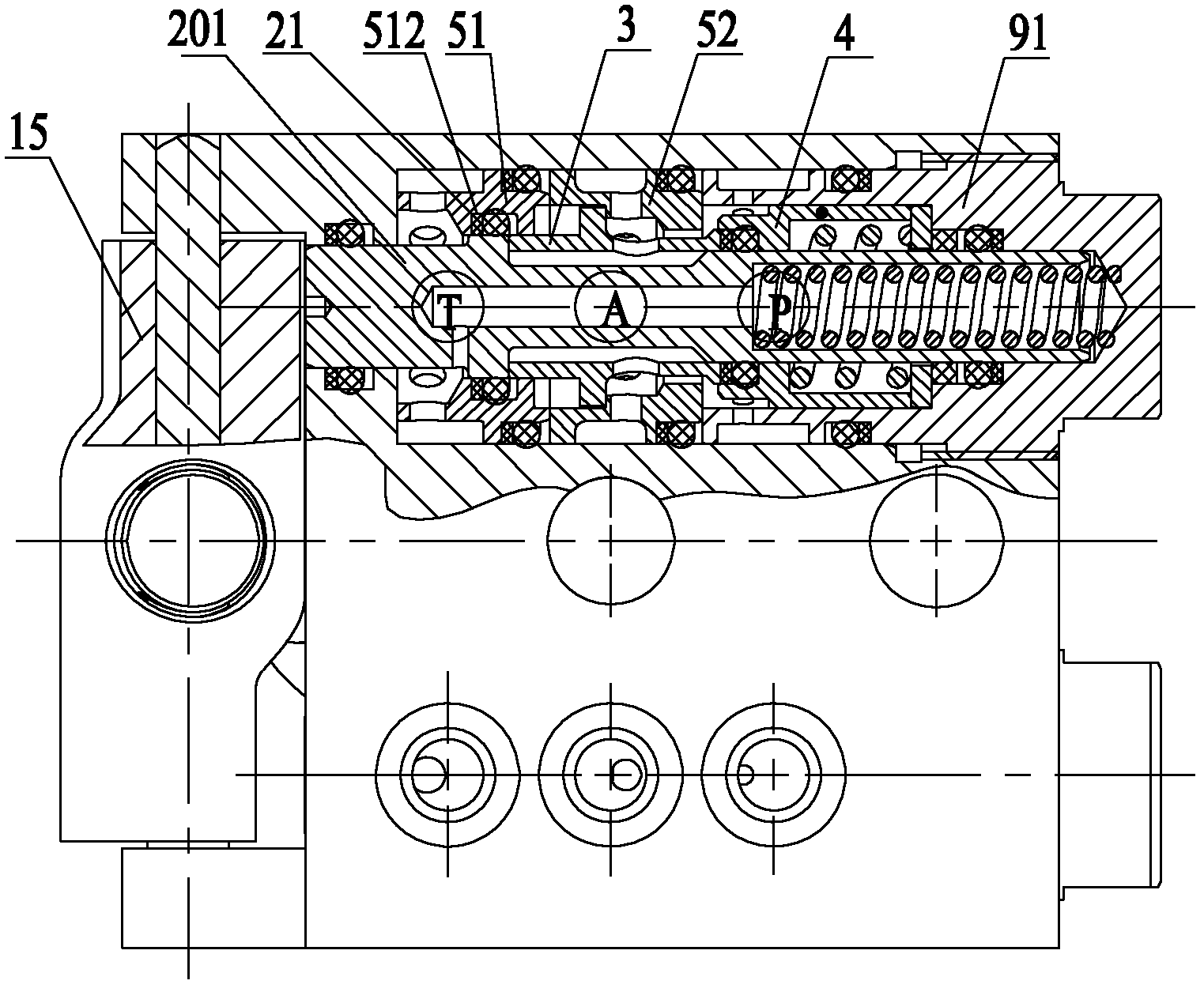
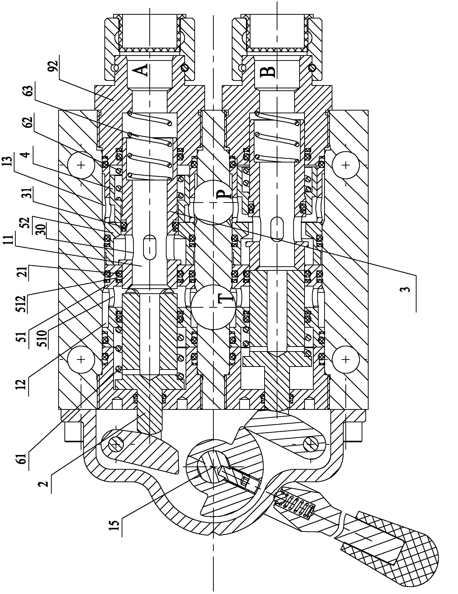
[0020] see Figure 1 to Figure 3 , shows the cross-sectional structure of the sealing structure of the manual reversing valve provided by the present invention. As shown in the figure, the manual reversing valve is provided with a working oil port A connected to the actuator, an oil return port T connected to the oil tank, and a high-pressure oil port P connected to the high-pressure oil source. The valve body 1 of the manual reversing valve is correspondingly formed with a working chamber 11, an oil return chamber 12 and a high pressure chamber 13, wherein the working chamber 11 communicates with the working oil port A, the oil return chamber 12 communicates with the oil return port T, and th...


PUM


Abstract

The invention provides a hand-operated reversing valve and a sealing structure thereof. The hand-operated reversing valve has a sealing structure, a liquid return main sealing element is positioned in a first annular cavity, and the inner circumferential wall and the outer circumferential wall of the liquid return main sealing element are respectively butted against and in contact with the inner circumferential wall and the outer circumferential wall of the first annular cavity; and/or a liquid feed main sealing element is positioned in a second annular cavity, and the inner circumferential wall and the outer circumferential wall of the liquid feed main sealing element are respectively butted against and in contact with the inner circumferential wall and the outer circumferential wall of the second annular cavity. Through the adoption of the technical scheme provided by the invention, the main sealing structure adopts a radial dynamic sealing manner, so as to greatly reduce the wear of the main sealing element, improve the antifouling capacity of the main sealing element and prolong the service life of the main sealing element. The hand-operated reversing valve provided by the invention is provided with the sealing structure of the above hand-operated reversing valve.

Description

technical field [0001] The invention relates to the field of control valves, in particular to a manual reversing valve and its sealing structure. Background technique [0002] The manual reversing valve is one of the most important hydraulic components of the hydraulic support used in coal mines. In the control system of the hydraulic support, it controls the direction of the liquid flow and realizes different actions of the hydraulic support. At present, the main seals (including the liquid return main seal and the liquid inlet main seal) between the oil return chamber, the working chamber and the high pressure chamber of the manual reversing valve mainly use conical soft seals, conical hard seals or flat soft seals, etc. For the main sealing structure, for example, the patent documents with the patent application numbers 201120175187 and 201120015319 respectively provide specific implementations of the main sealing structures of the conical surface seal and the flat soft s...

Claims


Application Information

Patent Timeline
Patent Type & Authority Applications(China)
IPC IPC(8): F15B13/02
Inventor 贾春强郑丽伟丁少华
Owner 益阳市科技成果转化服务中心
Why Eureka
Try Eureka