Method for measuring center thickness of reflective confocal lens

A technology of central thickness and confocal lens, which is applied in the direction of measuring devices, instruments, and optical devices, etc., can solve the problems of complex installation and adjustment process, and achieve the effect of reducing complexity, reducing the difficulty of installation and adjustment, and achieving tomographic capabilities

Inactive Publication Date: 2012-09-19
BEIJING INSTITUTE OF TECHNOLOGYGY
View PDF13 Cites 13 Cited by
  • Summary
  • Abstract
  • Description
  • Claims
  • Application Information

AI Technical Summary

Problems solved by technology

However, in this patent, the lens under test is placed in the converging beam, and the lens under test needs to be adjusted four-dimensionally during the measurement, so that its optical axis is completely consistent with the optical axis of the converging beam, and the assembly process is complicated.

Method used


Image

  • Method for measuring center thickness of reflective confocal lens
  • Method for measuring center thickness of reflective confocal lens
  • Method for measuring center thickness of reflective confocal lens

Examples


Embodiment 1

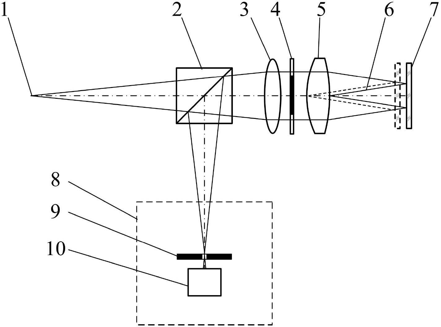
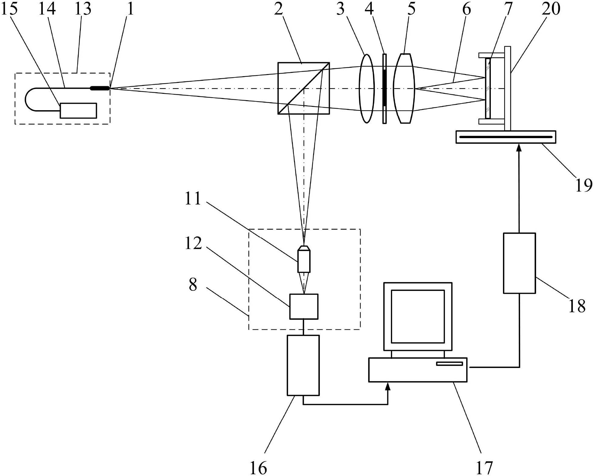
[0042] as attached figure 1 And attached figure 2 As shown, the measurement method for the central thickness of the reflective confocal lens, the measurement steps are:

[0043] (a) Start the measurement software in the main control computer 17, and input relevant parameters, which mainly include the radius of curvature r of the rear surface of the measured lens 5 2 =100.7134mm, air refractive index n 0 =1, the measured lens 5 refractive index n=1.5143 and the numerical aperture angle α of the measuring beam 6 0 =5.8°.

[0044] (b) Turn on the laser 15 , the light emitted by the laser 15 is transmitted through the optical fiber 14 to form the point light source 1 . The light emitted by the point light source 1 passes through the beam splitter 2 and the collimator lens 3 to form a parallel beam;

[0045] (c) Place the plane mirror 7 on the two-dimensional adjustment frame 20, adjust the plane mirror 7 through the two-dimensional adjustment frame 20, so that its surface is...

Embodiment 2

[0054] The difference from Embodiment 1 is that the annular pupil 4 is added to block the paraxial light in the method of measuring the central thickness of the reflective confocal lens, and then the measurement of the central thickness of the measured lens 5 is completed. Due to the addition of the annular pupil 4, the measurement beam 6 forms a hollow measurement light cone, which will effectively reduce the influence of aberrations on the measurement results.


PUM


Abstract

The invention belongs to the technical field of optical precision measurement, and relates to a method for measuring the center thickness of a reflective confocal lens. The method comprises the steps of precisely positioning the vertex of the front surface of the lens and the vertex of the rear surface of the lens by using a confocal measurement method and a plane mirror, and obtaining the center thickness of the lens according to a ray tracing formula. High-precision fixed focus collimation of the vertex of the front surface and the vertex of the rear surface of the measured lens is realized by utilizing light rays emitted by the measured lens for the first time, and adopting the confocal technology, difficulty in adjustment of the measured lens is reduced to a great extent, and the method has the advantages of high measurement precision and environmental interference resistance, and can be used for precisely measuring center thicknesses of the lenses.

Description

technical field [0001] The invention belongs to the technical field of optical precision measurement and can be used for non-contact high-precision measurement of lens center thickness. technical background [0002] In an optical system, a lens is one of the most basic and important components, and its optical performance will directly affect the overall performance of the system. Therefore, in order to ensure that the overall performance of the optical system meets the requirements, strict tolerance requirements will be imposed on the parameters of each lens used. Among all the parameters of the lens, the central thickness of the lens is one of the most basic and important parameters, and its processing accuracy will directly affect the comprehensive performance of the lens such as focal length and aberration, and then affect the performance of the entire optical system. And with the emergence of cutting-edge projects such as lithography machines and nuclear fusion optical...

Claims


Application Information

Patent Timeline
Patent Type & Authority Applications(China)
IPC IPC(8): G01B11/06
Inventor 邱丽荣杨佳苗赵维谦邵荣君李佳李雅灿
Owner BEIJING INSTITUTE OF TECHNOLOGYGY
Why Eureka
Try Eureka