Multi-cavity filter taking coupled dual-gap cavity

A basic unit, double-gap technology, applied to waveguide devices, electrical components, circuits, etc., can solve the problems of large size, high cost, narrow 1dB bandwidth of filters, etc., and achieve small size, reduced volume, and high transmission power capacity Improved effect

Inactive Publication Date: 2012-09-19
GUANGDONG UNIV OF TECH +1
View PDF5 Cites 10 Cited by
  • Summary
  • Abstract
  • Description
  • Claims
  • Application Information

AI Technical Summary

Problems solved by technology

[0003] The purpose of the present invention is to overcome the problems of narrow 1dB bandwidth, large volume and high cost of the existing coaxial cavity filter, and provide a cavity filter with coupled doubl

Method used


Image

  • Multi-cavity filter taking coupled dual-gap cavity
  • Multi-cavity filter taking coupled dual-gap cavity
  • Multi-cavity filter taking coupled dual-gap cavity

Examples


Embodiment Construction

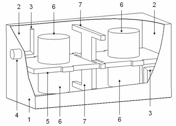
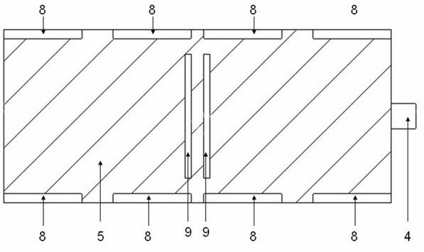
[0016] refer to figure 1 , 2 , the present invention proposes a multi-cavity filter with a coupled double-gap cavity as the basic unit, and through continuous optimization of the cavity structure and each coupling hole, a GSM-1800 transmission frequency band that can work in a wide range of applications is designed (1805 ~ 1880MHz) requires a multi-cavity filter with a coupled double-gap cavity as the basic unit. The most successful feature of this filter is that it uses a coupled double-gap cavity with an upper and lower double-layer structure as the basic unit, and uses a "T"-shaped coupling wall between the two coupled double-gap cavities to realize the coupling between adjacent cavities. This double-gap cavity structure and coupling method can not only effectively reduce the number of resonant units, but also obtain a larger transmission bandwidth.

[0017] The filter is composed of two coupled double-gap cavities 2 on the left and right surrounded by a cavity shell 1. T...


PUM


Abstract

The invention discloses a multi-cavity filter taking a coupled dual-gap cavity as a basic unit. The multi-cavity filter consists of two or more coupled dual-gap resonant cavity basic units enclosed by a cavity shell. The problems of narrow 1dB bandwidth and large size of the conventional coaxial cavity filter are solved; a wide 1dB bandwidth can be obtained by using a few cavity units; the provided metal cavity filter is high in power, wide in frequency band, small in size and light in weight; and the strength of coupling between every two cavities is optimal, and a high-power microwave filter meeting the bandwidth requirements of a mobile communication base station filter is designed.

Description

technical field [0001] The invention relates to the technical field of microwave filters, in particular to a multi-cavity filter with coupled double-gap cavities as basic units. Background technique [0002] Due to its advantages of good electromagnetic shielding, compact structure, low insertion loss in the passband, small size and high power capacity, metal cavity filters have long been the first choice for mobile communication base station transmit filters. Multi-coaxial cavity cross-coupled metal cavity filters are widely used in current mobile communication systems due to their good filtering characteristics and easy tuning. However, while modern wireless communication base stations are constantly pursuing higher performance indicators, Smaller size and lower cost are also pursued, and coaxial cavity metal cavity filters have certain technical bottlenecks in terms of reducing size and improving 1dB bandwidth. For this reason, after full investigation and analysis, ...

Claims


Application Information

Patent Timeline
IPC IPC(8): H01P1/208
Inventor 林福民赵培伟
Owner GUANGDONG UNIV OF TECH
Why Eureka
Try Eureka