
Permanent-magnet rotor with embedded magnetic steels

A technology of permanent magnet rotor and magnet steel, applied in the direction of magnetic circuit rotating parts, magnetic circuit shape/style/structure, etc., can solve the problem of unreliable axial fixation of magnet steel, rotor can not produce air convection, and the consumption of electromagnetic materials increases and other problems, to achieve the effect of reliable axial fixation of magnetic steel, simple and reasonable structure, and reduced consumption

Active Publication Date: 2014-12-10
FOSHAN WEILING WASHER MOTOR MFG
View PDF2 Cites 0 Cited by
  • Summary
  • Abstract
  • Description
  • Claims
  • Application Information

AI Technical Summary

Problems solved by technology

[0003] This kind of permanent magnet rotor embedded in magnetic steel has the following three disadvantages: 1) The rotor has no special parts for dynamic balancing. When the rotor is dynamically balanced, only the outer circle of the rotor core can be milled, or the end face of the rotor core can be milled. Drilling, and these solutions will change the magnetic circuit of the motor, resulting in an imbalance in the magnetic circuit, causing electromagnetic vibration and electromagnetic noise; In occasions with strict temperature rise requirements, it will lead to an increase in the amount of electromagnetic materials; 3) Affected by the assembly process and working environment, the fixing agent has the risk of failure, and the axial fixing method of the magnetic steel is unreliable, which may loosen and cause the motor to fail

Method used


Image

  • Permanent-magnet rotor with embedded magnetic steels
  • Permanent-magnet rotor with embedded magnetic steels
  • Permanent-magnet rotor with embedded magnetic steels

Examples


Embodiment Construction

[0025] The present invention will be further described below in conjunction with the accompanying drawings and embodiments.

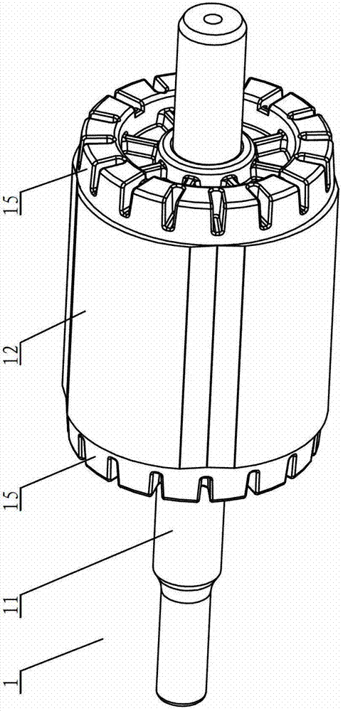
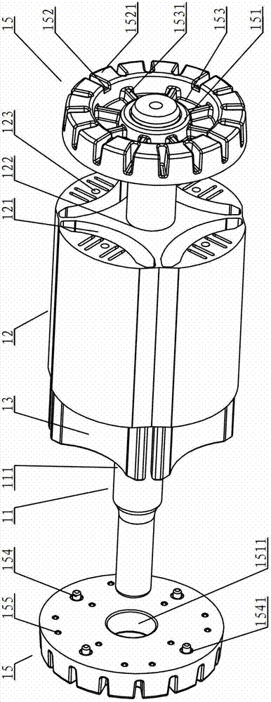
[0026] see Figure 2-Figure 3 , the permanent magnet rotor embedded in the magnetic steel includes a rotor core 12 sleeved on the rotor shaft 11, the magnetic steel 13 is inserted on the rotor core 12, and the rotor core 12 is provided with a sleeve sleeved on the rotor shaft. 11 on the balance ring 15, the balance ring 15 is made of non-magnetic material. In this embodiment, there are two balance rings 15 , which are respectively arranged on the two sides of the rotor core 12 .

[0027] One side of the balance ring 15 is provided with an inner ring 151 and an outer ring 152 , the inner ring 151 and the outer ring 152 are connected by more than two reinforcing ribs 1531 , and counterbores 153 are arranged between adjacent reinforcing ribs 1531 . The ribs 1531 are evenly arranged. In this embodiment, the number of reinforcing ribs 1531 may be 3-15, an...


PUM


Abstract

A permanent-magnet rotor with embedded magnetic steels comprises a rotor core sleeved on a rotor shaft. The magnetic steels are inserted on the rotor core, balancing rings sleeved on the rotor shaft are arranged beside the rotor core and made of non-magnetic conductive materials, an inner ring and an outer ring are arranged on one side of each balancing ring, each inner ring is connected with the corresponding outer ring through more than two reinforcing ribs, counter bores are arranged between each two adjacent reinforcing ribs, each outer ring is provided with more than two uniformly distributed and projecting petal blocks, more than one projecting positioning boss is arranged at the other end of each balancing ring, corresponding positioning holes are arranged on the rotor core, the positioning bosses are inserted into the positioning holes, more than one projecting boss is further arranged at the other end of each balancing ring and arranged on the end faces of the magnetic steels by means of pressure welding, and the number of the bosses is not less than that of the magnetic steels. The permanent-magnet rotor with the embedded magnetic steels has the advantages of simple and reasonable structure, axial fixing reliability of the magnetic steels, low electromagnetic vibration and noise, low temperature rise and less electromagnetic material consumption.

Description

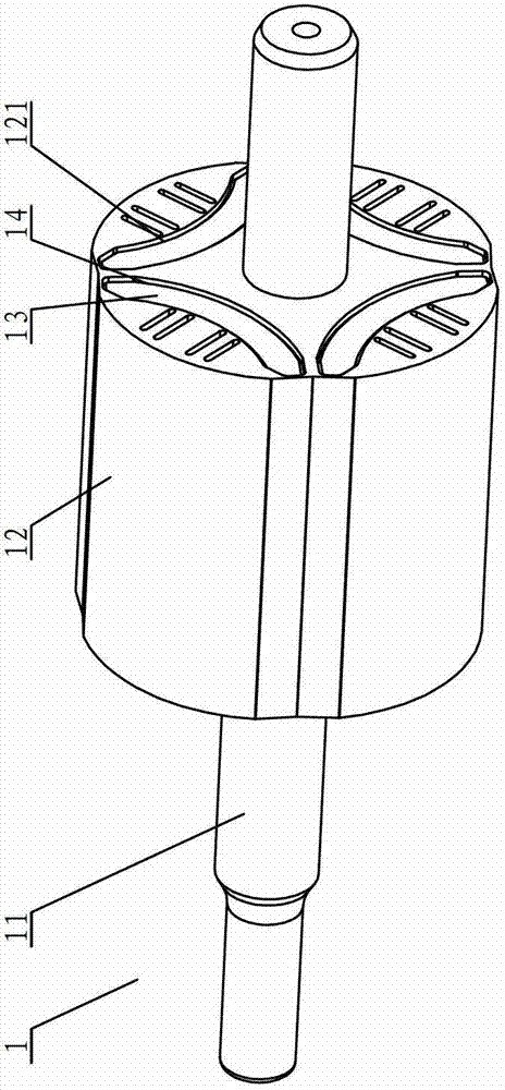
technical field [0001] The invention relates to a permanent magnet rotor, in particular to a permanent magnet rotor embedded in magnetic steel. Background technique [0002] The permanent magnet rotor 1 embedded in traditional magnetic steel, as attached figure 1 As shown, it consists of a rotor shaft 11, a rotor core 12, a magnet 13 and a fixative 14. The rotor core 12 is provided with an installation hole 121 for installing the magnet, and there is a gap between the installation hole 121 and the magnet 13. In cooperation, the fixing agent 14 is coated in the gap between the magnetic steel 13 and the installation hole 121 , and the magnetic steel 13 and the rotor core 12 are fixed together when the fixing agent 14 is cured. [0003] This kind of permanent magnet rotor embedded in magnetic steel has the following three disadvantages: 1) The rotor has no special parts for dynamic balancing. When the rotor is dynamically balanced, only the outer circle of the rotor core can b...

Claims


Application Information

Patent Timeline
Patent Type & Authority Patents(China)
IPC IPC(8): H02K1/27
Inventor 王松陈勋彬
Owner FOSHAN WEILING WASHER MOTOR MFG
Learn More