Pasting method for machine vision-based irregular electronic device

A technology for electronic components and components, which is applied in the direction of assembling printed circuits with electrical components, and can solve the problems of high price, high price, and time-consuming machine adjustment of imported chip mounters.

Inactive Publication Date: 2012-09-19
李正标
View PDF3 Cites 30 Cited by
  • Summary
  • Abstract
  • Description
  • Claims
  • Application Information

AI Technical Summary

Problems solved by technology

At present, my country is still unable to produce high-grade placement machines. Imported placement machines are expensive, and most of the structures used are orthogonal structures composed of servo motors driving bal...

Method used


Image

  • Pasting method for machine vision-based irregular electronic device
  • Pasting method for machine vision-based irregular electronic device
  • Pasting method for machine vision-based irregular electronic device

Examples


Embodiment Construction

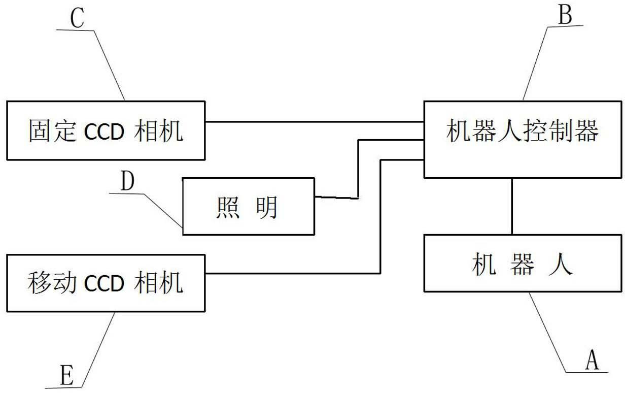
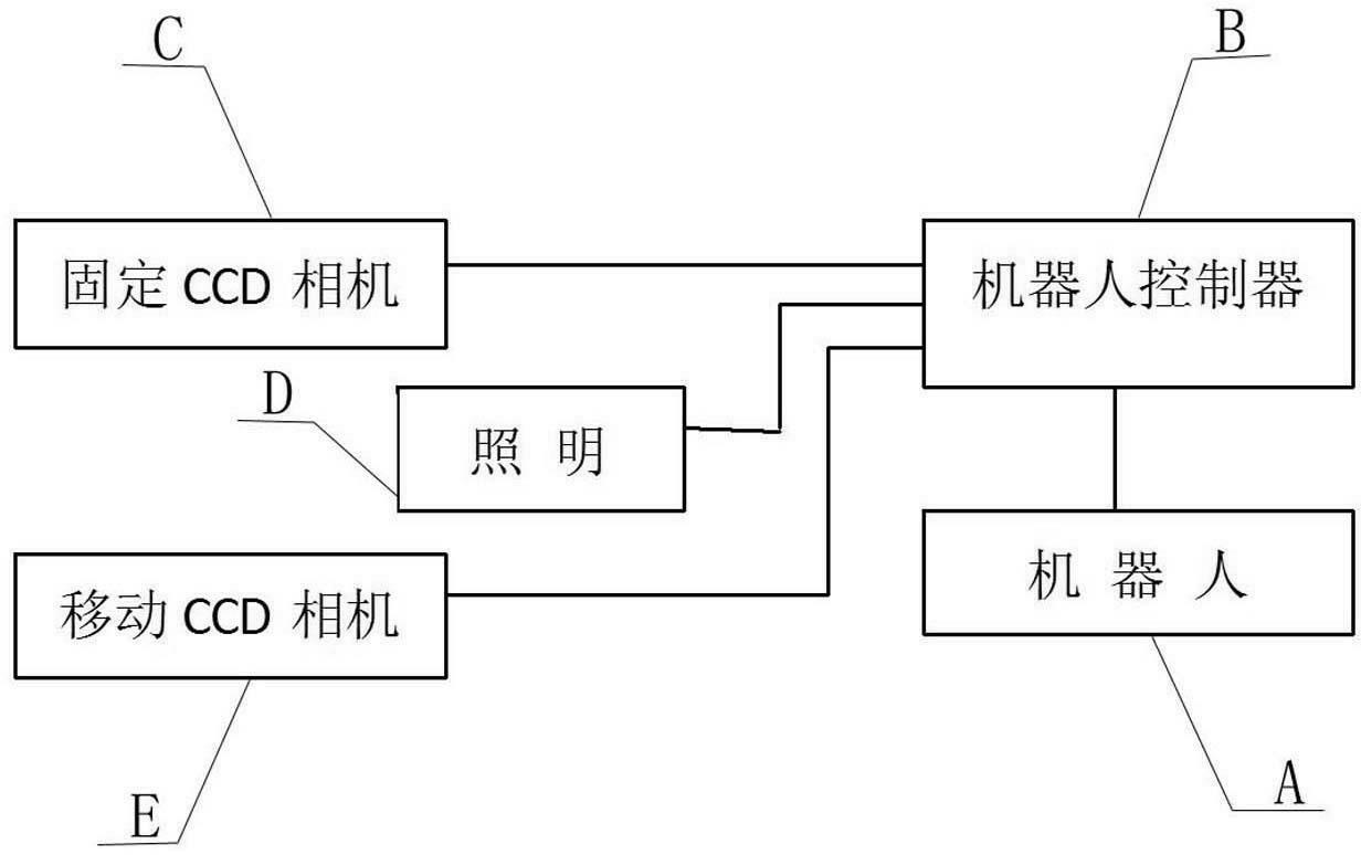
[0009] Such as figure 1 As shown, the placement robot includes a mobile CCD camera, a fixed CCD camera, a robot controller, a robot body and a lighting fixture. The fixed CCD camera is installed in the working range of the manipulator and installed downwards. A mobile CCD camera is installed within the working range of the manipulator. The CCD camera adopts the edge search method, and the special-shaped electronic components can be searched even if they are partly outside the field of view. components. The robot controller has its own vision software, which receives the coordinate values ​​of the mobile CCD camera and the fixed CCD camera about the PCB board and special-shaped electronic components, and transmits the instructions to the robot for execution after correction. The robot body is a 4-axis multi-joint horizontal robot. During the working process of the robot, the deviation between the center value of the R-axis of the robot and the center value of the fixture sh...


PUM


Abstract

The invention relates to a pasting device for electronic devices in electronic industry. Pasting task is completed by robots. The pasting device consists of a robot A, a robot controller B, a fixed CCD (charged coupled device) camera C, an illuminator D, and a mobile CCD camera E. The pasting method comprises the steps that the robot detects feeding of a PCB (Printed Circuit Board), the mobile CCD cameras takes a picture to record a first MARK point position of the PCB, and the mobile CCD cameras takes a picture to record a second MARK point position, vision software calculates and regulates the target coordinates of the robot, the target coordinates of the robot are regulated along with position change of the PCB, the fixed CCD camera takes a picture to record the standard position of the irregular device, the vision software conducts correction and converts into the standard coordinates of the robot, the fixed CCD camera takes a picture to record the coordinates of the irregular device after being moved, positions of the internal points of the robot controller are regulated, the current coordinates and the standard coordinates of the device are compared, angles and translation are sequentially corrected, and the irregular device with the corrected coordinates is moved to the target coordinates of the PCB. In the method, the pasting machine is replaced with the robot, so that the investment is saved and the pasting efficiency is improved.

Description

technical field [0001] The invention relates to a patching device for electronic components in the electronics industry, and particularly relates to a low-cost and high-efficiency patching method for electronic components with irregular physical shapes. Background technique [0002] The placement of electronic components on the PCB board of the electronics industry, the equipment currently used at home and abroad is a placement machine, which has high production efficiency and is suitable for mass production. At present, my country is still unable to produce high-grade placement machines. Imported placement machines are expensive, and most of the structures used are orthogonal structures composed of servo motors driving ball screws. [0003] For the production of multiple varieties and small batches, the traditional special-shaped placement machine has disadvantages such as high price and time-consuming machine adjustment when changing varieties. These issues are yet to be ...

Claims


Application Information

Patent Timeline
IPC IPC(8): H05K3/30
Inventor 李正标李明亮张平良
Owner 李正标
Why Eureka
Try Eureka