Fluid power machine

A power machine and fluid technology, applied in the direction of engines, wind engines, machines/engines, etc., can solve the problems of large transmission shock and unstable operation, and achieve the effects of stable operation, large frontal flow area, and high fluid kinetic energy utilization rate.

Inactive Publication Date: 2012-09-26
廖宝书
View PDF9 Cites 0 Cited by
  • Summary
  • Abstract
  • Description
  • Claims
  • Application Information

AI Technical Summary

Problems solved by technology

[0003] The purpose of the present invention is to provide a fluid power machine, which can solve the problems of large transmission impact and unstable operation in the existing fluid power devices that can automatically change the windward surface of the blades

Method used


Image

  • Fluid power machine
  • Fluid power machine
  • Fluid power machine

Examples


Embodiment Construction

[0019] The present invention will be described in further detail below in conjunction with accompanying drawing embodiment:

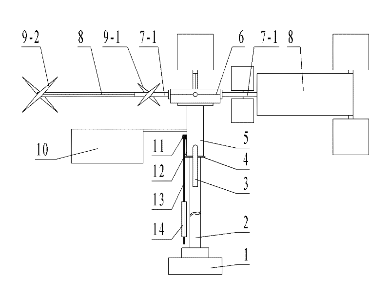
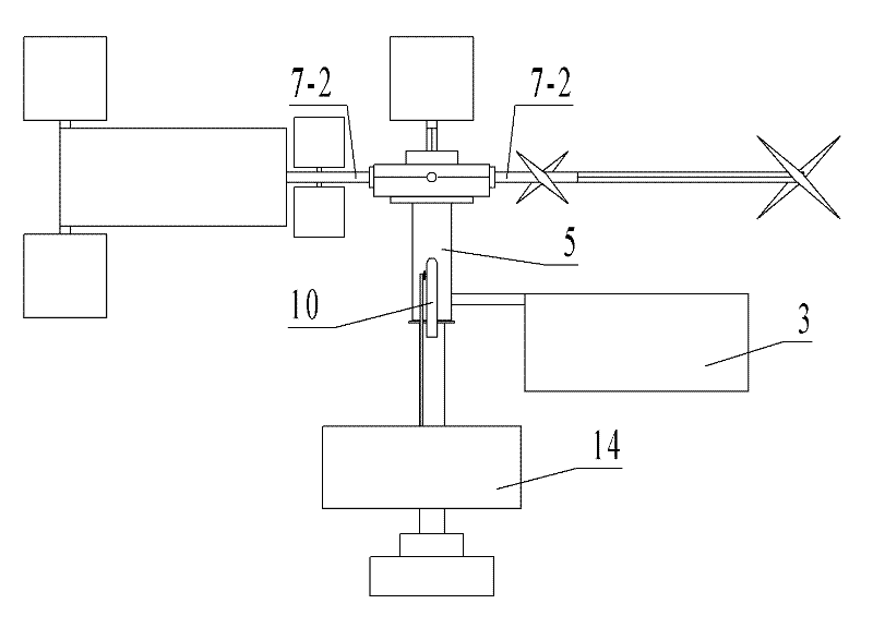
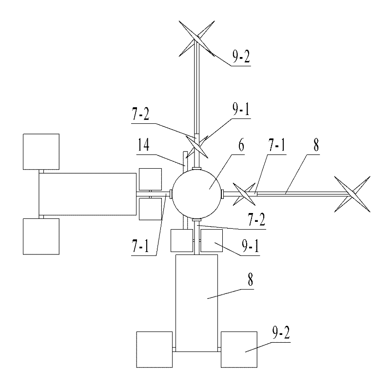
[0020] This embodiment includes an organic base 1, a hollow shaft 2, a balance plate 3, an orifice plate 4, a rudder plate hinge 5, a blade shaft frame 6, a blade shaft A7-1, a blade shaft B7-2, a main drive blade 8, and an auxiliary drive Blade 9, rudder plate 10, suspension plate gear 11, lock pin 12, swing lever 13, driving suspension plate 14, output shaft 15, cam 16, blade shaft joint A17-1, blade driving gear A17-11, blade shaft joint B17 -2, blade drive gear B17-21, double-tooth movable rack 18-1, single-tooth movable rack 18-2, cam drive pin 19, guide wheel 20, dust cover 21.

[0021] Figure 1 to Figure 5 The fluid power machine shown includes an output shaft 15, main drive blades 8, a hollow shaft 2 and a base 1, the hollow shaft 2 is welded on the base 1, the output shaft 15 is sleeved in the hollow shaft 2, and the hollow shaft 2 is A slee...


PUM


Abstract

The invention discloses a fluid power machine which comprises a hollow shaft, an output shaft, blade shaft brackets, blade shafts, main drive blades, a sleeve, a rudder plate and a rudder plate direction lock device. Each blade shaft is meshed with a movable rack arranged on the blade shaft brackets through a blade drive gear; a rudder plate hinge element is fixedly connected with a cam; two cam drive pins fixedly connected with the movable rack are arranged on the wheel face of the cam, and a balance plate arranged at one side of the rudder plate is fixedly connected with the rudder plate hinge element. Compared with the prior art, the power machine has the advantages of small transmission impact, stable operation, high reliability, more rational structure, convenience for manufacture, installation and maintenance, longer service life, simple and reliable lock blade structure and more accurate direction location of the fluid, and the effective utilization rate of fluid power and the power of the power machine can ne improved.

Description

technical field [0001] The invention relates to the technical field of mechanical manufacturing, in particular to a mechanical device capable of converting fluid kinetic energy such as wind energy and water energy into mechanical energy. Background technique [0002] In the prior art, most power mechanical devices that convert fluid kinetic energy into mechanical energy use bladed rotor structures such as impellers to output rotational mechanical energy in response to fluid flow. When the impeller rotates in the fluid, the inclination angle of the blades on the impeller remains constant during the rotation process, and the rotational area of ​​the impeller occupies a large fluid channel, and the utilization rate of fluid kinetic energy in the channel is low. In order to overcome the above-mentioned problems, the applicant invented a rudder direction variable impeller machine, and submitted a Chinese patent application on June 20, 2011, and its application publication number...

Claims


Application Information

Patent Timeline
IPC IPC(8): F03D1/06F03B3/14
CPCY02E10/223Y02E10/721Y02E10/20Y02E10/72Y02P70/50
Inventor 廖宝书
Owner 廖宝书
Why Eureka
Try Eureka