Valveless piezoelectric pump with axisymmetric logarithmic spiral pipe

A valveless piezoelectric pump and logarithmic screw technology, applied in the direction of pumps, pump components, variable capacity pump components, etc., can solve the problems of energy consumption reduction, unfavorable integration and miniaturization, complex structure, etc., and achieve one-way Effects of reduced pressure loss, ease of integration and miniaturization, and improved volumetric efficiency

Inactive Publication Date: 2012-09-26
JIANGSU UNIV
View PDF7 Cites 17 Cited by
  • Summary
  • Abstract
  • Description
  • Claims
  • Application Information

AI Technical Summary

Problems solved by technology

[0003] Commonly used diffusion/contraction tube valveless piezoelectric pumps include "Y" tube valveless piezoelectric pumps and "V" tube valveless piezoelectric pumps, and the inlet and outlet flow tubes of "Y" tube valveless piezoelectric pumps It consists of a confluence pipe and two diversion pipes forming a "Y" shape. The confluence pipe and the diversion pipe are all rectangular pipes with equal cross-sections. The inlet flow pipe of the "V" tube valveless piezoelectric pump is composed of a rectangular pipe with equal cross-section as the confluence pipe and two diffuse (shrink) shunt pipes. The defect is that the inlet and outlet flow pipes and the pump chamber ar

Method used


Image

  • Valveless piezoelectric pump with axisymmetric logarithmic spiral pipe
  • Valveless piezoelectric pump with axisymmetric logarithmic spiral pipe
  • Valveless piezoelectric pump with axisymmetric logarithmic spiral pipe

Examples


Embodiment Construction

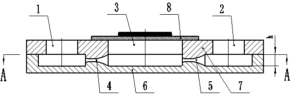
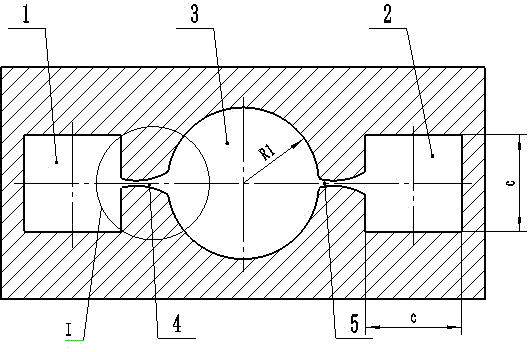
[0020] Such as Figure 1-3 , the present invention includes a pump body 6, a pump cover 7 and a piezoelectric vibrator 8, the pump body 6 and the pump cover 7 are electrostatically bonded together, the piezoelectric vibrator 8 is fixed directly above the pump cover 7 by an adhesive, and the pump cover 7 The pump inlet 1 and the pump outlet 2 are processed on the top, and the pump inlet 1 and the pump outlet 2 are respectively connected to the inlet pipe and the outlet pipe; the MEMS processing technology is used to process two inlet flow pipes 4 with the same structure on the pump body 6 and the pump cover 7 , outlet flow tube 5 and a cylindrical pump cavity 3, wherein the pump cavity 3 is located between the inlet flow tube 4 and the outlet flow tube 5, and the inlet flow tube 4, the outlet flow tube 5 and the pump cavity 3 are coaxial in the horizontal direction , the inlet flow pipe 4 and the outlet flow pipe 5 communicate with the pump chamber 3 respectively, and the three...


PUM

PropertyMeasurementUnit
Diameteraaaaaaaaaa

Abstract

The invention relates to a valveless piezoelectric pump, more particularly to a valveless piezoelectric pump with axisymmetric logarithmic spiral pipes. The valveless piezoelectric pump with axisymmetric logarithmic spiral pipes comprises a pump body, a pump cover and a piezoelectric vibrator. An inlet flow tube, an outlet flow tube and a pump chamber are provided on the pump body. The inlet flow tube and the outlet flow tube have the same structure, are arranged coaxially, and are concentric and equidistant with the pump chamber center. The inlet flow tube and the outlet flow tube are both axisymmetric logarithmic spiral pipes. Profiles of the axisymmetric logarithmic spiral pipes are logarithmic spiral lines defined by a logarithmic spiral curve equation: rho = rho0 * e<k theta>. The pump of the invention has the main advantages of small scale, simple structure, easy miniaturization, capability of acquiring stable pressure, steady flow inside the pump with almost no eddy, and no damage to a transmission medium. Compared with valveless piezoelectric pumps with other structures, the valveless piezoelectric pump with axisymmetric logarithmic spiral pipes has lower unidirectional flow resistance and higher forward and reverse flow resistance coefficient ratio. Thus, the pump has higher volumetric efficiency, more stable flow can be obtained, and energy loss is significantly reduced.

Description

technical field [0001] The invention relates to a valveless piezoelectric pump, in particular to an axisymmetric logarithmic spiral tube valveless piezoelectric pump. Background technique [0002] Piezoelectric pump is a kind of mechanical micropump, which belongs to positive displacement pump. It is widely used in the fields of micro-transportation of drugs, cell separation, cooling of electronic products, micro-injection of fuel, chemical micro-analysis, transition control of pipeline flow, etc. At present, piezoelectric pumps mainly There are two types of piezoelectric pumps with valves and piezoelectric pumps without valves. Due to the existence of valves, piezoelectric pumps with valves will cause a large pressure loss when the fluid passes through the valves, and it is too difficult to start the water injection process, and it is difficult to process and integrate. It is relatively large, which limits the development of the piezoelectric pump to a more miniaturized dir...

Claims


Application Information

Patent Timeline
IPC IPC(8): F04B43/04F04B53/16
Inventor 何秀华邓志丹蔡盛川
Owner JIANGSU UNIV
Why Eureka
Try Eureka