Shafting hot alignment device and shafting hot alignment method

A technology for thermal alignment and shafting, which is applied to measuring devices, electrical devices, instruments, etc., can solve the problems that affect the accurate acquisition of thermal alignment data, unstable and constant rotation of shafting, and take a certain amount of time. Achieve the effect of improving measurement work efficiency, ensuring measurement accuracy, and avoiding manual turning

Active Publication Date: 2012-09-26
SHANGHAI HENGTUO IND DEV
View PDF4 Cites 10 Cited by
  • Summary
  • Abstract
  • Description
  • Claims
  • Application Information

AI Technical Summary

Problems solved by technology

[0008] 1. Immediately turn on the brake and stop, then open the casing, and set up tools to measure the alignment data. The process takes a certain amount of time instead of instantaneous measurement. The measured alignment data is not accurate in the thermal state;
[0009] 2. Although the dial indicator is the most conventional measuring tool, the division value is 0.001mm or 0.002mm, and the indication value range is generally 0~10mm, but due to a series of reasons such as installation and human reading errors, there are always certain errors in the obtained data , there is a bottleneck if the accuracy needs to be further improved;
[0010] 3. Manual cranking is required to obtain alignment data during the process. Manual cranking makes the rotation of the shaft system unstable and constant, and varies from person to person, so it will also affect the accurate acquisition of thermal alignment data to a certain extent.

Method used


Image

  • Shafting hot alignment device and shafting hot alignment method
  • Shafting hot alignment device and shafting hot alignment method
  • Shafting hot alignment device and shafting hot alignment method

Examples


Embodiment Construction

[0031] The present invention will be further described below in conjunction with the accompanying drawings and embodiments.

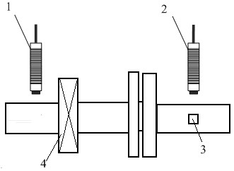
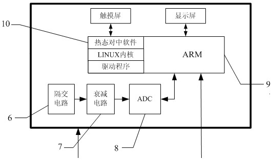
[0032] Such as figure 1 , As shown in 2, the shafting thermal centering device of the present invention includes an eddy current sensor 1, a rotational speed sensor 2, an isolation circuit 6, a signal attenuation circuit 7, an ADC analog-to-digital conversion circuit 8, and an ARM main control chip 9, etc.

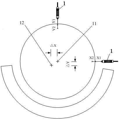
[0033] Arrange a transverse and vertical eddy current sensor 1 at the position of the bearing 4 of the shafting or near the shaft where the centering position of the unit needs to be adjusted, which are used to measure the transverse gap and vertical gap of the shafting system respectively, and on the shaft where the centering position needs to be adjusted Paste a reflective paper 3, and set a speed sensor 2 corresponding to the reflective paper 3, which is used to mark the angle of the key phase. The eddy current sensor 1 is connected to the input...


PUM


Abstract

The invention relates to a shafting hot alignment device and a shafting hot alignment method. Horizontal and vertical eddy current sensors are disposed at shafting bearing positions or alignment required positions of a unit around a journal. The horizontal and vertical eddy current sensors are used to measure shafting lateral clearance and vertical clearance respectively. Reflecting paper is adhered to a shaft at the alignment required position, and a revolution speed sensor corresponds to the reflecting paper is used for keyway-phase angle marking. Lateral clearance and vertical clearance value signals of the shafting of the eddy current sensor acquisition unit are processed by an alternating current blocking circuit and a signal attenuation circuit and are then transmitted into an ADC (analog to digital converter) and converted into digital signals, and the digital signals are transmitted to a rear-end ARM (advanced RISC machines) master control chip. When the shafting of the revolution speed sensor acquisition unit rotates to the reflecting paper, a signal of instant phase marking angle value is output, a square signal is output to the ARM master control chip, the signals are subjected to difference calculation by the ARM master control chip through hot alignment software, and data signal of shafting position compensation value required by hot alignment is output to a data output device.

Description

technical field [0001] The invention relates to a centering device for each rotor axis in mechanical equipment, in particular to a centering device for equipment shafting in a hot state. Background technique [0002] Shafting and rotor misalignment is one of the most common faults in rotating machinery. It is mainly caused by alignment variation errors such as axis parallel displacement, axis angular displacement or comprehensive displacement between the rotor axes of the machine. The shaft system where the rotor is misaligned not only changes the mutual position of the rotor journal and the bearing and the working state of the bearing, but also reduces the natural frequency of the shaft system. The misalignment of the shafting rotor, the force on the rotor and the additional force on the support are important reasons for the abnormal vibration of the shafting and early damage to the bearing. Therefore, each equipment is aligned in a cold state during assembly, installation...

Claims


Application Information

Patent Timeline
Patent Type & Authority Applications(China)
IPC IPC(8): G01B7/14
Inventor 符栋梁王强李国平陈长盛柳瑞锋冯海军
Owner SHANGHAI HENGTUO IND DEV
Why Eureka
Try Eureka