Device and method for detecting microbending loss of optical fiber
An optical fiber and microbending technology, applied in the field of microbending loss detection, can solve the problems of adding optical fibers, inaccurate positioning, inaccurate formation, etc., and achieves the effects of good repeatability, high accuracy and simple operation.
- Summary
- Abstract
- Description
- Claims
- Application Information
AI Technical Summary
Problems solved by technology
Method used
Image
Examples
Embodiment 1
[0022] Embodiment 1 The structure of the device for detecting optical fiber microbending loss according to the present invention
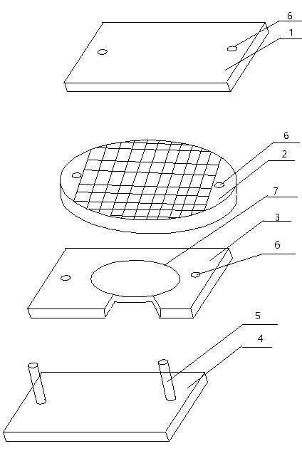
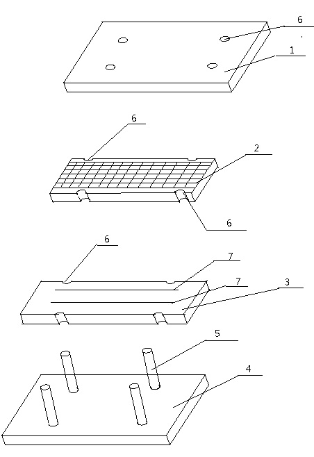
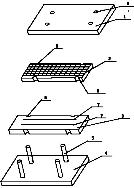
[0023] The device for detecting optical fiber microbending loss of the present invention includes a metal cover plate 1, a metal grid 2, a rubber plate 3 and a metal base 4 provided with a positioning column 5, the metal cover plate 1, the metal grid 2 and the rubber plate 3 are provided with positioning holes 6 that match the positioning columns 5, and two marking lines 7 with a distance of 20-30 mm and a length of 145-155 mm are also provided on the rubber plate 3. The metal grid 2 The length is the same as the marked line length.
[0024] There are four positioning columns 5 on the metal base 4, and four positioning holes 6 on the metal cover plate 1, the metal grid 2 and the rubber plate 3 respectively.
[0025] The metal grid 2 is rectangular.
Embodiment 2
[0026] Embodiment 2 Method for detecting optical fiber microbending loss by using the device of the present invention
[0027] In the detection process, in addition to the device for detecting the microbending loss of the optical fiber of the present invention, a pillar and an optical power meter are also required. The diameter of the column is 60-200 mm, preferably 60 mm.
[0028] The method for detecting optical fiber microbending loss using the device of the present invention is to place the device for detecting optical fiber microbending loss between the pillar and the optical power meter, and the rubber plate 3 is fixed on the metal base 4. The method also includes the following steps:
[0029] (1) Leave 40-50cm of the free end of the optical fiber to be tested to connect to the optical power meter, and then fix the subsequent optical fiber on one of the marking lines 7 with adhesive tape under the condition of no force, and then wind along the column Filter out the high...
Embodiment 3
[0035] Embodiment 3 The comparison between the method of the present invention and the original metal grid method to detect the microbending loss of optical fiber
[0036] 20 samples were taken from the same optical fiber, and tested by the method of the present invention and the original metal grid method, and the test data of the two methods were compared. In the optical power meter used (1310nm light source is generally used for multi-single-mode fiber, and 1550nm light source is generally used for single-mode fiber), the method of filtering out high-order film (loosely winding a circle on a column with a diameter of 60mm), rubber plate (with a hardness of 75 ), the metal grid (specification 70 mesh), and the weight of the metal cover are the same, only the weight of the weight added to the metal cover is changed, and the test results obtained are as follows:
[0037] Table 1 The test results when the weight of the heavy object on the metal cover is 2kg
[0038] ...
PUM
| Property | Measurement | Unit |
|---|---|---|
| Diameter | aaaaa | aaaaa |
| Diameter | aaaaa | aaaaa |
| Length | aaaaa | aaaaa |
Abstract
Description
Claims
Application Information
 - R&D
- Intellectual Property
- Life Sciences
- Materials
- Tech Scout
- Unparalleled Data Quality
- Higher Quality Content
- 60% Fewer Hallucinations
Browse by: Latest US Patents, China's latest patents, Technical Efficacy Thesaurus, Application Domain, Technology Topic, Popular Technical Reports.
© 2025 PatSnap. All rights reserved.Legal|Privacy policy|Modern Slavery Act Transparency Statement|Sitemap|About US| Contact US: help@patsnap.com


