
Non-scanning method for acquiring CT (Computer Tomography) projection data

A projection data, non-scanning technology, used in measuring devices, instruments, scientific instruments, etc., can solve the problems of unsuitable rotation scanning method measurement, reconstructed image errors, etc.

Active Publication Date: 2012-09-26
吴桂琴
View PDF3 Cites 0 Cited by
  • Summary
  • Abstract
  • Description
  • Claims
  • Application Information

AI Technical Summary

Problems solved by technology

[0002] In the existing CT technology, regardless of whether the beam incident on the measured object is a straight line, a fan or a cone, and whether the detector is a single, linear array or area array, the scanning method of rotating the measured object or CT measurement components is used. Obtaining projection data from different angles (Yikeshilang International Ray Co., Ltd. CT method for collecting projection data: China, 200610140311.3[P]. 2007-05-30; Shanghai Institute of Applied Physics, Chinese Academy of Sciences. A fast X Radiation fluorescence CT method: China, 201010171983.7[P].2010-10-20), cannot use a single beam pulse with a very short duration (for example, within one millisecond) to acquire CT projection data in the range of 180° projection angles
In CT measurement, the rotation speed of the mechanical structure is generally less than 50 cycles per second. If the measured object changes or moves during the measurement process, it will cause errors in the reconstructed image
Some measured objects are not suitable to be irradiated by the beam for a long time, and it is not suitable to use the rotating scanning method for measurement

Method used


Image

  • Non-scanning method for acquiring CT (Computer Tomography) projection data
  • Non-scanning method for acquiring CT (Computer Tomography) projection data
  • Non-scanning method for acquiring CT (Computer Tomography) projection data

Examples


Embodiment Construction

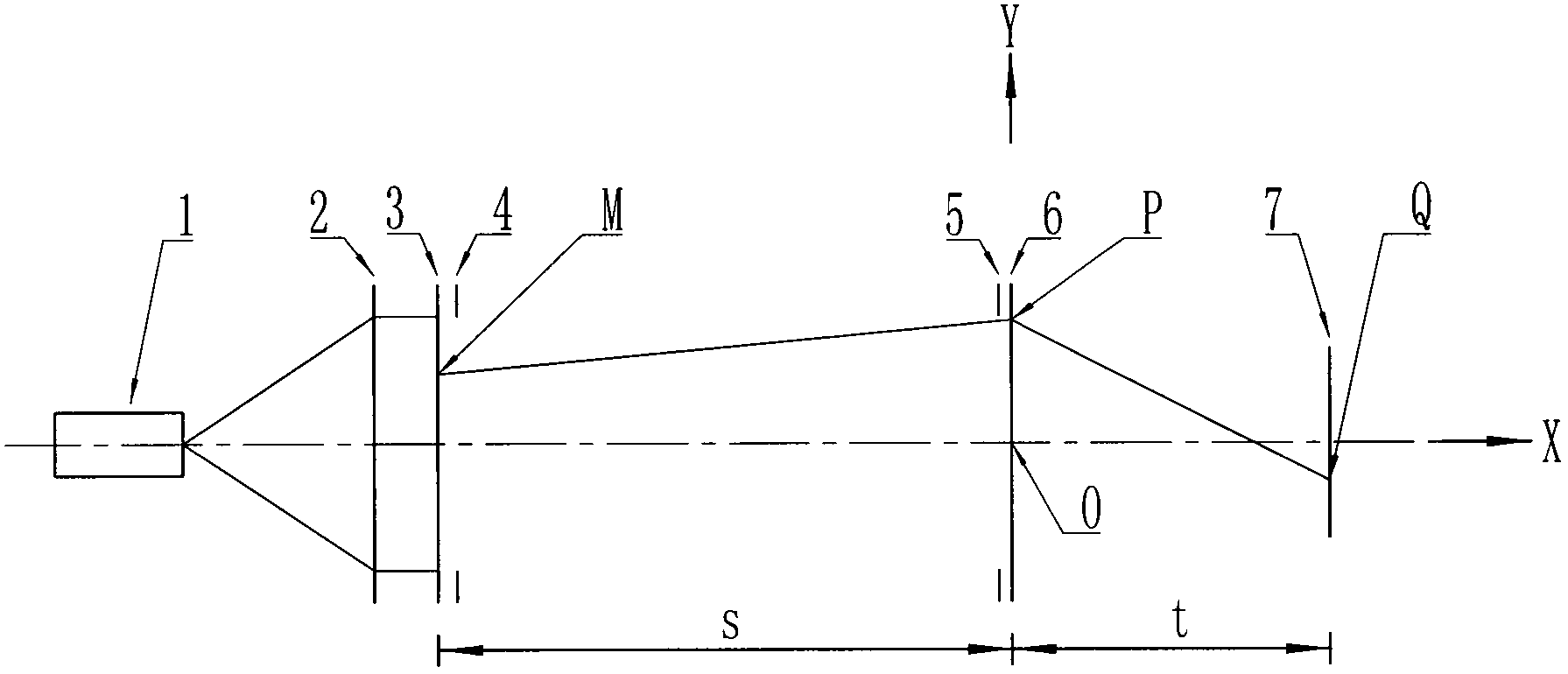
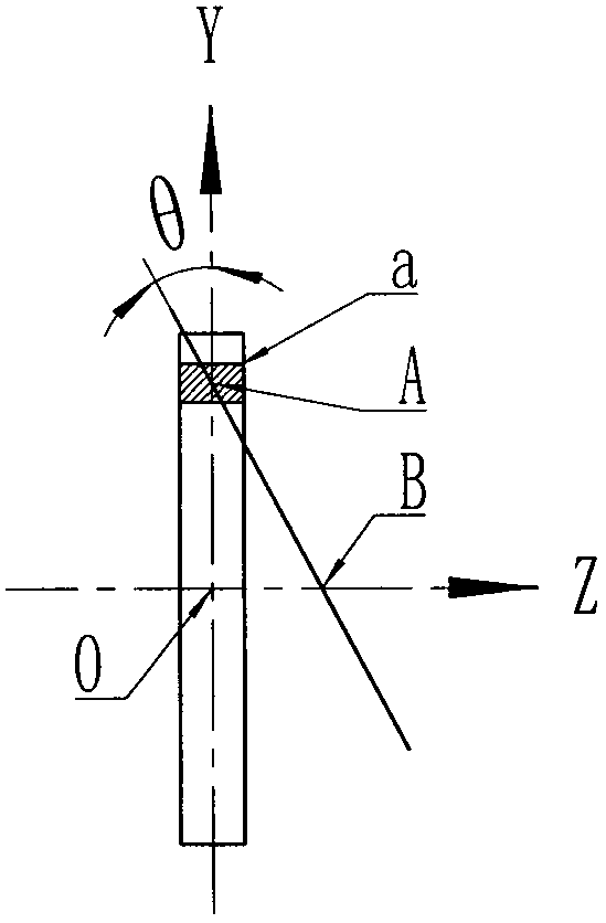
[0012] The point beam source 1, shaping lens group 2, diffuser 3, exit slit 4, incident slit 5, deflection lens 6, and plane detector 7 are attached according to the axis of symmetry of the X axis. figure 1 The arrangement shown constitutes a CT measurement unit, wherein the exit slit 4 is close to the diffuser 3 , the entrance slit 5 is close to the deflection lens 6 , and the test area is between the exit slit 4 and the entrance slit 5 . A CT measurement component can measure certain The projection data of the angle range, a CT measurement system composed of multiple CT measurement components, can be used The measurement range reaches 180°, which meets the requirements of image reconstruction for projection angle. During measurement, the point beam source 1 emits a beam, and the beam passes through the shaping lens group 2, the diffuser 3, the exit slit 4, the measured object, the entrance slit 5 and the deflection lens 6 and then irradiates to the On the receiving surfa...


PUM


Abstract

The invention relates to a non-scanning method for acquiring CT (Computer Tomography) projection data, and the non-scanning method is suitable for measuring sectional images of a measured object which is in rapid change and rapid motion and inappropriate for long-term beam irradiation. According to the non-scanning method for acquiring the CT projection data, the measured object and a plurality of CT measurement components are not required for rotation and translation. The CT measurement components consist of linear diffusion beam sources, beam deflectors and planar detectors; beams shot from the linear diffusion beam sources pass through the measured object and are then deflected by the beam deflectors; two-dimensional flux density distribution is formed on the planar detectors; the two-dimensional flux density distribution comprises a number of groups of parallel beam lines, a number and spacing distance of the parallel beam lines of each group, and projection angle information corresponding to the parallel beam lines of each group; and the information is the CT projection data. One CT measurement component can be used for measuring data in a range of a certain projection angle, and a CT measurement system consisting of the CT measurement components can be used for measuring the projection data in the range of 180 DEG. When pulse beams are used, the pulse duration is beam irradiation time.

Description

technical field [0001] The invention relates to a non-scanning method for collecting CT projection data without rotation and translation of both the object to be measured and the CT measurement component. Background technique [0002] In the existing CT technology, regardless of whether the beam incident on the measured object is a straight line, a fan or a cone, and whether the detector is a single, linear array or area array, the scanning method of rotating the measured object or CT measurement components is used. Obtaining projection data from different angles (Yikeshilang International Ray Co., Ltd. CT method for collecting projection data: China, 200610140311.3[P]. 2007-05-30; Shanghai Institute of Applied Physics, Chinese Academy of Sciences. A fast X Radiation fluorescence CT method: China, 201010171983.7[P].2010-10-20), cannot use a single beam pulse with a very short duration (for example, within one millisecond) to collect CT projection data in the range of 180° pr...

Claims


Application Information

Patent Timeline
IPC IPC(8): G01N23/04G01N23/083
Inventor 吴桂琴
Owner 吴桂琴
Learn More