Pin type plug seedling transplanting end effector

A technology of end effector and plug seedlings, which is applied in the field of agricultural machinery, can solve the problems of large resistance to entry into the soil, long size of the end effector, and large operation resistance, etc., and achieve smooth entry into the soil, good versatility, and good force transmission characteristics Effect

Inactive Publication Date: 2012-10-03
JIANGSU UNIV
View PDF10 Cites 32 Cited by
  • Summary
  • Abstract
  • Description
  • Claims
  • Application Information

AI Technical Summary

Problems solved by technology

The end effector for transplanting plug seedlings developed by Tian Subo, Zhang Lihua, Yin Wenqing, etc. Journal of Agricultural University, 2010, 04, 41(2): 235-237; Yin Wenqing et al. End effector of dry land plug seedling transplanting machine. Publication number: CN101569257A) Use a single cylinder or motor to drive the vertical movement of fingers to take seedlings and Falling seedlings, in order to meet the needs of clamping seedlings when picking seedlings in the inner hole tray, the fingers are designed to have a certain radian and inclination angle, and at the same time, the fingers produce a certain deformation when entering the soil to pick seedlings, due to the gap between the finger movement direction and the fingertip direction There is an included angle, and as the finger deforms, the included angle becomes larger, resulting in excessive resistance to entry into the soil
At the same time, its vertical linear motion structure causes the end effector itself to be too long
Transplanting end effector developed by K. C. Ting et al. et al. Workability and Productivity of Robotic Plug Transplanting Workcell. Vitro Cell. Dev. Biol.1992, 28:5-10) The cylinder drives the swing of the fingers to achieve soil entry and clamping, and the constant change of the finger angle after entry into the soil brings operational resistance increase and the instability of clamping seedling lumps, and may cause a gap between the seedling lumps and the soil at the same time, which will have an adverse effect on the healthy growth of seedlings
The four types of end effectors developed by Huang Shixin et al. are all driven by electromagnets (Huang Shixin et al. Design and performance analysis of clamps for seedling transplantation. Journal of Agricultural Machinery, 1996, 5 (3): 51-65), among which The finger-shaped end effector uses two electromagnets to realize the finger insertion and clamping respectively. The drive is more complicated and the flake fingers must be inserted into the soil strictly against the edge of the seedling hole; the three types of needle-shaped finger end effectors are driven by a single electromagnet. , but the fingers or fingertips are tilted, and there is also an angle between the direction of finger movement and the direction of the fingertips, resulting in excessive resistance to entry into the soil
[0003] Therefore, the existing end effectors for transplanting seedlings at home and abroad have problems such as complex drive and transmission, high cost, and large operating resistance. At the same time, the inclination angle of the fingers and the clamping size are not easy to adjust, and cannot adapt to different tray specifications and different crop seedlings. Automated transplanting requirements

Method used


Image

  • Pin type plug seedling transplanting end effector
  • Pin type plug seedling transplanting end effector
  • Pin type plug seedling transplanting end effector

Examples


Embodiment Construction

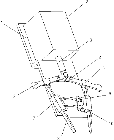
[0013] Such as figure 1 As shown, the pin-type hole tray seedling transplanting end effector consists of a housing back plate 1, an electromagnet 2, an electromagnet push rod 3, two horizontal groove inner sliders 4, two swing rod sliders 5, two It consists of a swing rod 6, two sliding sleeves 7, two pins 8, two upper bolts and nuts 9 and two lower bolts and nuts 10.

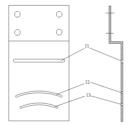
[0014] Such as figure 2 As shown, the housing back plate 1 is provided with a horizontal slot 11 , and a large arc slot 12 and a small arc slot 13 . The horizontal slot 11, the large arc slot 12, and the small arc slot 13 are all left-right symmetrical, and the common center of the large arc slot 12 and the small arc slot 13 is located below the centerline of the shell back plate 1.

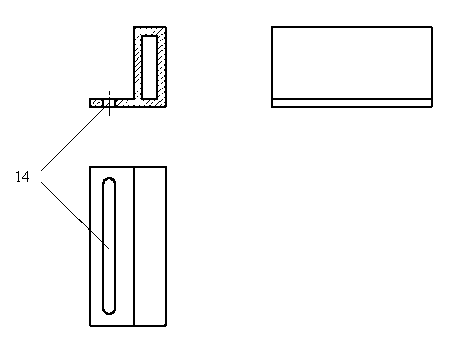
[0015] Such as image 3 As shown, the sliding sleeve 7 is provided with a coupling through groove 14 .

[0016] The electromagnet 2 is fixed on the shell back plate 1, and the electromagnet push rod 3 protrudes from the elect...


PUM


Abstract

The invention discloses a pin type plug seedling transplanting end effector, which belongs to the field of agricultural machinery. The pin type plug seedling transplanting end effector consists of a shell back plate, an electromagnet, an electromagnet push rod, two horizontal in-groove slide blocks, two swing link slide blocks, two swing links, two slide bushings, two pins, two upper bolt and nuts and two lower bolts and nuts, wherein the electromagnet is electrified to drive the electromagnet push rod to extend out so as to drive the swing links to swing; and the pins extend out towards the diagonal lower side along a straight line determined by the fixed slide bushings through sliding of the swing link slide blocks so as to be plugged into plug holes to pick up a seedling. When a seedling heap is clamped by the pin type plug seedling transplanting end effector to reach a seedling placement position, the pin type plug seedling transplanting end effector descends to plant the seedling heap into soil, the electromagnet is powered off, and the spring in the electromagnet drives the electromagnet push rod to automatically reset, so that the two pins are driven to retract into the slide bushings in reverse directions, and the seedling heap is pressed by the bottom ends of the slide bushings; and thus, the seedling heap is prevented from being brought out again by friction force when the sliding pins retract to guarantee the quality of transplantation. The movement direction of the pins of the pin type plug seedling transplanting end effector is fixed, so that good force transfer characteristic is guaranteed, and the pins are inserted into the soil smoothly; the angle for inserting the pins into the soil and the clamping opening are adjustable, so that good universality is achieved; and thus, smooth insertion for picking up and placing the seedlings during transplantation of various plug seedlings is realized with a simple structure.

Description

technical field [0001] The invention relates to the field of agricultural machinery, in particular to an end effector for transplanting seedlings in plug-in plugs. Background technique [0002] The end effector of plug seedling transplanting is the key device for the automatic plug seedling transplanting machine and transplanting robot to directly insert into the hole to take seedlings and complete the seedling release. It has become the focus of research on intelligent and automatic transplanting technology at home and abroad. Plug seedling transplanting end effector developed by Wang Xiaoyu, Sun Guoxiang, Jiang Huanhuang, Zhou Ting, L.G. Kutz, W. C. Choi, etc. Design of end effector of seedling transplanting machine and analysis of virtual prototype. Journal of Agricultural Machinery, 2010, 41 (10): 48-53, 47; etc. Design and Simulation Analysis of Greenhouse Tray Seedling Transplanting Machine. Mechanical Design and Research, 2009, 25 (2): 121-124; L.G. Kutz, et al. Robo...

Claims


Application Information

Patent Timeline
Patent Type & Authority Applications(China)
IPC IPC(8): A01C11/02
Inventor 刘继展李萍萍毛罕平
Owner JIANGSU UNIV
Why Eureka
Try Eureka