Yarn guiding device

A yarn guide device and yarn guide technology, applied in the direction of textiles and papermaking, etc., can solve problems such as difficult operation, poor quality of yarn finished products, complex structure, etc., and achieve improved yield and yarn quality, good yarn quality, Even twist effect

Active Publication Date: 2015-04-22
单水甫
View PDF13 Cites 1 Cited by
  • Summary
  • Abstract
  • Description
  • Claims
  • Application Information

AI Technical Summary

Problems solved by technology

[0006] The invention provides a simple structure, which is convenient for threading and connecting silk threads, and can directly form strand air circle twist-stop points at the outlets of hot-melt threads and multi-strand sewing threads, and can accurately coat the hot-melt threads on multi-strand sewing threads. A yarn guide device in the middle of the sewing thread; it solves the problem in the prior art that the thermal fuse cannot be accurately wrapped in the middle of the multi-strand sewing thread, and the yarn outlet cannot directly form the twist-stop point of the strand balloon. The integrated structure is complicated, the operation is difficult, the waste of raw materials and labor, and the technical problems of poor quality of the final yarn product

Method used


Image

  • Yarn guiding device
  • Yarn guiding device
  • Yarn guiding device

Examples


Embodiment 1

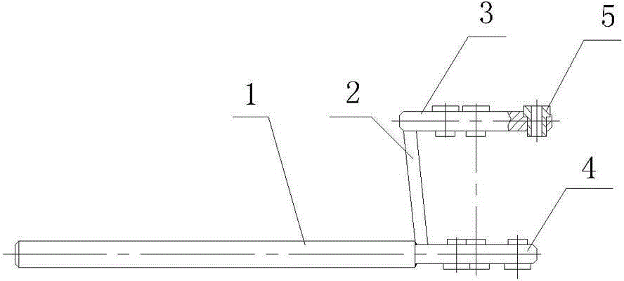
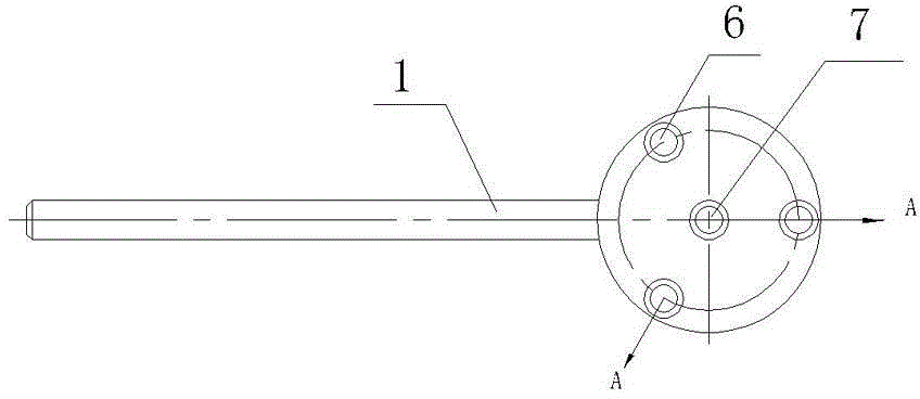
[0024] Such as figure 1Shown, a kind of yarn guiding device comprises circular upper fixed plate 3 and circular lower fixed plate 4, the upper and lower fixed plates are parallel to each other, the diameter of upper fixed plate 3 is greater than the diameter of lower fixed plate 4, and upper fixed plate 3 The distance with the lower fixing plate 4 is 33mm. The upper fixed plate 3 and the lower fixed plate 4 are connected to each other by a connecting rod 2, the width of the connecting rod 2 is only 1 / 8 of the side area of ​​the circular platform space surrounded by the upper and lower fixed plates, and the upper and lower fixed plates and the connecting rod 2 are One piece. A fixed rod 1 is fixed on the outer edge of the lower fixed plate 4, and the end of the fixed rod 1 intersects with the connection point of the connecting rod 2 on the lower fixed plate 4, and the yarn guide is connected on the support part 21 of the frame by the fixed rod 1. Such as figure 2 As shown, ...

Embodiment 2

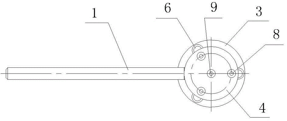
[0027] Such as Figure 5 As shown, the difference from Embodiment 1 is that the upper holes 6 on the upper fixing plate 3 and the lower holes 8 on the corresponding lower fixing plate 4 are alternately arranged, that is, the upper and lower fixing plates in Embodiment 1 are rotated by an angle. , the connection line between one of the lower hole 8 and the lower center hole 9 on the lower fixing plate 4 is projected onto the upper fixing plate 3, and the line between the projection line and the corresponding lower hole and the lower center hole on the upper fixing plate The angle θ between them is 8°. That is, the yarn passing through the upper hole and the lower hole produces an offset when going from the upper hole to the lower hole, forming a spiral-like rotating package. All the other are identical with embodiment 1.


PUM


Abstract

The invention relates to textile machinery components, particularly to a yarn guiding device, which comprises an upper fixed plate and a lower fixed plate arranged in parallel, wherein center holes are both formed in the centers of the upper fixed plate and the lower fixed plate; more than three upper edge holes and lower edge holes are formed on the upper fixed plate and the lower fixed plate; a distance from the upper center hole to the upper edge holes on the upper fixed plate is larger than that from the lower center hole to the lower edge holes on the lower fixed plate; and yarn guides are arranged in the upper and lower center holes and the upper and lower edge holes. The yarn guiding device has the advantages that the structure is simple, silk yarns can be threaded conveniently, and compound yarn ballooning check twisting points can be directly formed on silk outlets of thermotropic silk and multistrand sewing threads. The yarn guiding device can precisely cover thermotropic silk quilt covers among the multistrand sewing threads, and therefore, the yarn guiding device solves the technical problems that in the prior art, the thermotropic silk quilt covers can not be covered among the ultistrand sewing threads precisely, the silk outlets can not directly form the compound yarn ballooning check twisting points, assembled structures are complex, the operation is difficult, and raw material and labor force are wasted, so that finished products of the yarns have poor quality.

Description

technical field [0001] The invention relates to textile machine components, in particular to a yarn guiding device used for twisting yarns and thermal fuses into strands. Background technique [0002] With the high-speed development of sewing and weaving, the requirements for yarn diversification are getting higher and higher. As an important component of textile machinery, the yarn guide device has been deeply developed and researched. It has an inseparable relationship with the structure of the yarn guiding device. In the existing patent documents, there are many patent documents about the yarn guide device, such as the Chinese patent: "Yarn guide device (CN2481730Y)", which is applied to a fiber sheet to be kneaded into a thread, and utilizes a spindle for the silk thread For a winding action, a cohesive area is formed between the fiber sheet and the silk thread, which includes a conveying mechanism, which is used to transport the fiber sheet to the cohesive area, and a ...

Claims


Application Information

Patent Timeline
Patent Type & Authority Patents(China)
IPC IPC(8): D01H13/04
Inventor 单水甫
Owner 单水甫
Why Eureka
Try Eureka