Natural gas hydrate exploiting method

A mining method and hydrate technology, applied in the fields of fluid mining, mineral mining, earthwork drilling, etc., can solve the problems of low heat and mass transfer characteristics, low conductivity, low mining efficiency, etc. The effect of large flow conductivity and increased contact area

Active Publication Date: 2012-10-03
CHINA UNIV OF PETROLEUM (EAST CHINA)
View PDF4 Cites 26 Cited by
  • Summary
  • Abstract
  • Description
  • Claims
  • Application Information

AI Technical Summary

Problems solved by technology

[0009] The technical problem to be solved by the present invention is to provide a natural gas hydrate production method to solve the problem

Method used


Image

  • Natural gas hydrate exploiting method
  • Natural gas hydrate exploiting method
  • Natural gas hydrate exploiting method

Examples


Embodiment 1

[0023] Embodiment 1, the method for exploiting natural gas hydrate by injecting hot water:

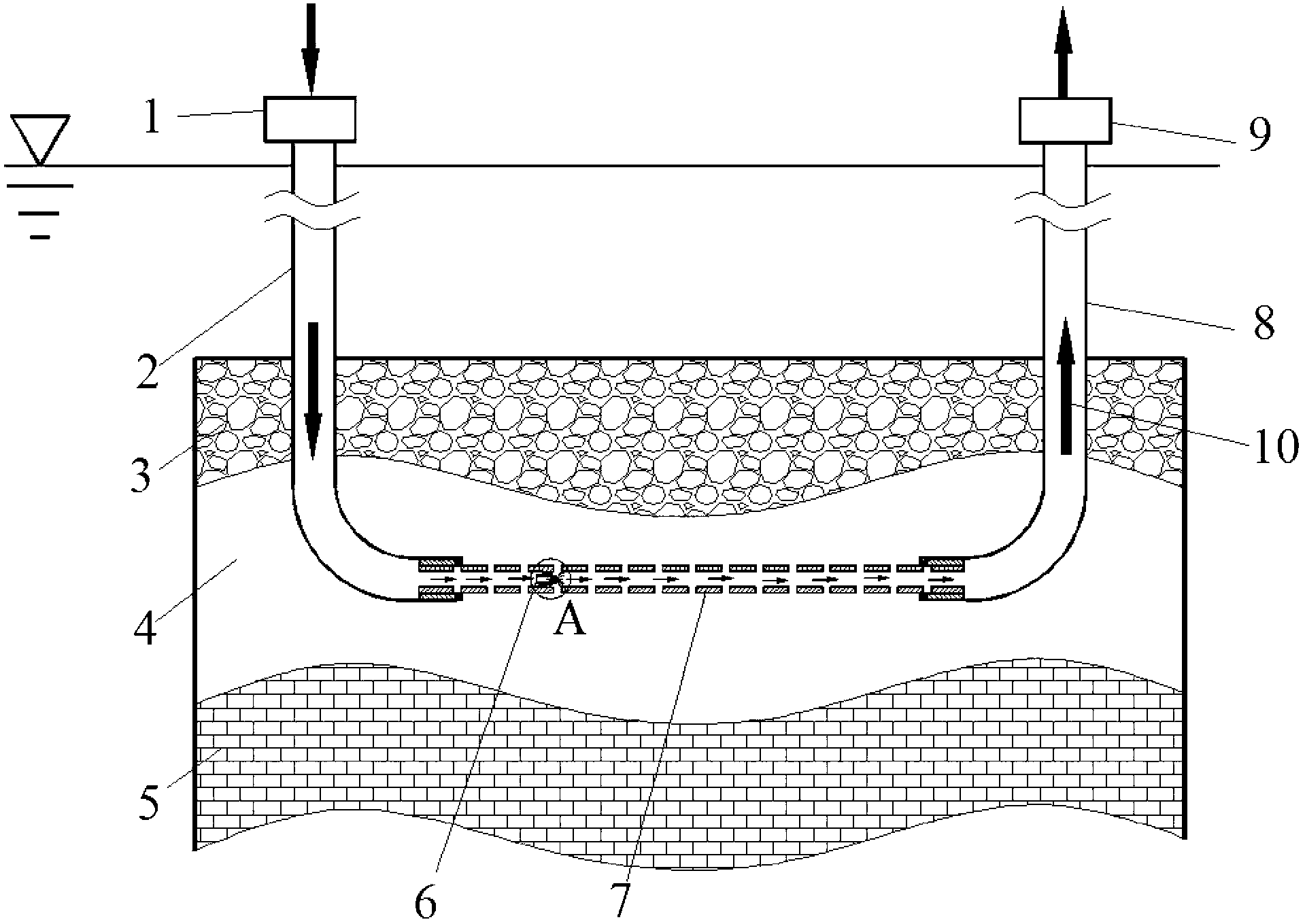
[0024] (1) if figure 1 As shown, a connecting well is drilled in the hydrate reservoir, the length of the horizontal section is 200-500 m, and the screen 7 is used to complete the entire horizontal section.

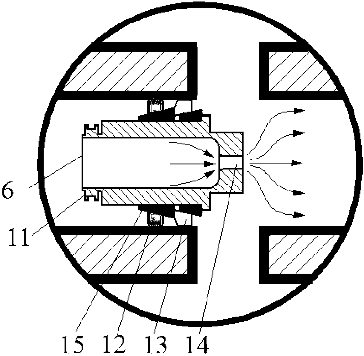
[0025] (2) Insert the throttling device 6 in the screen pipe (such as figure 2 shown), the throttling device 6 is installed at a distance of 1 / 5-2 / 5 from the injection well, and the slips 12 are set to push the wedge-shaped body 15 to move, thereby making the rubber tube 13 seal the throttling device 6 and the screen pipe 7 between the annular spaces.

[0026] (3) 60-300m from injection well 1 3 The hot water at 60-95°C is injected at the injection rate per day, and when it flows through the throttling device 6, a low pressure is generated behind the throttle nozzle 14. Under the double excitation of the low pressure and the injected hot fluid, the hydrate decomposition starts...

Embodiment 2

[0029] Example 2, the method of injecting hydrate decomposition accelerator to exploit hydrate:

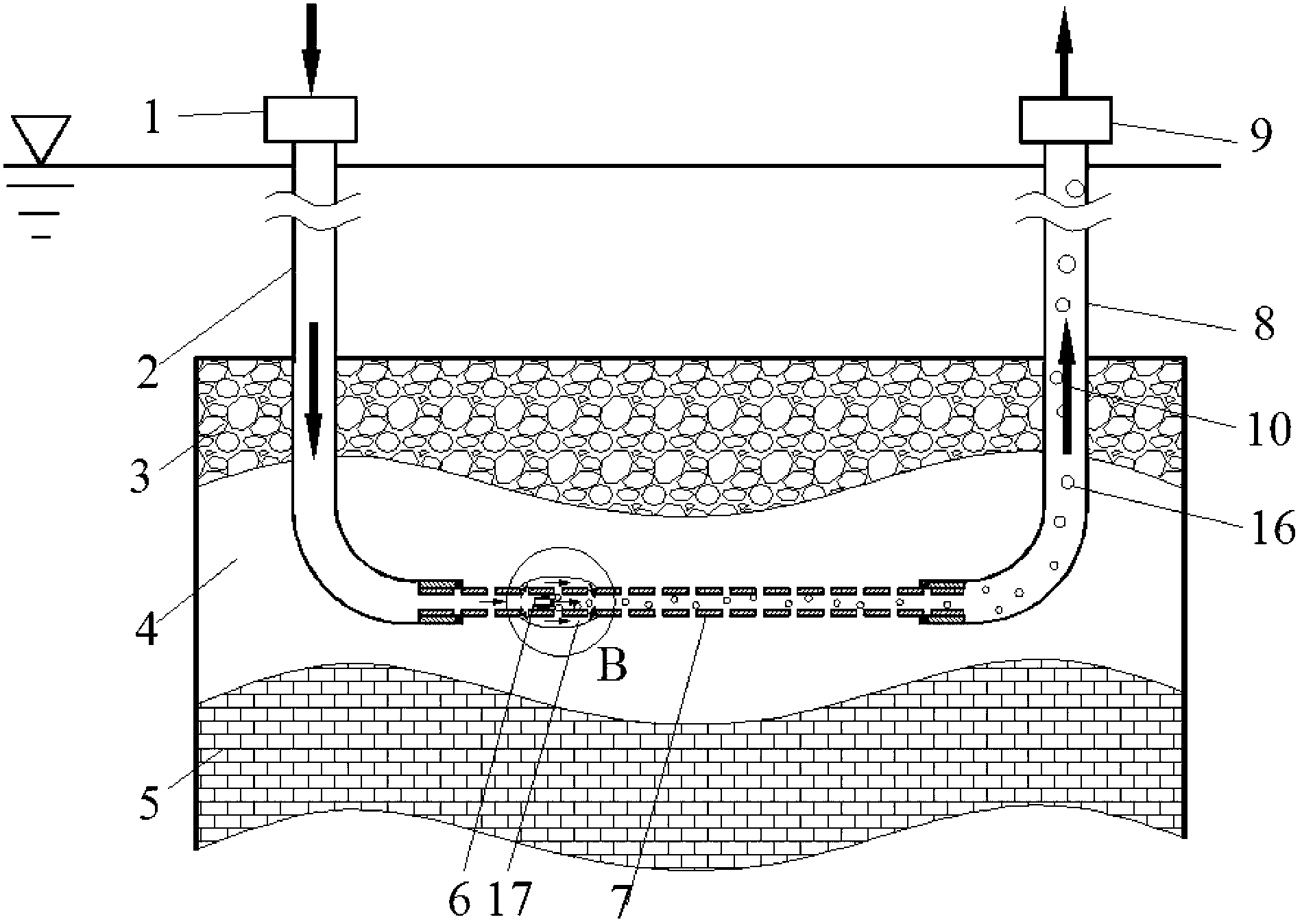
[0030] (1) if figure 1 As shown, a connecting well is drilled in the hydrate reservoir, the length of the horizontal section is 200-500 m, and the screen 7 is used to complete the entire horizontal section.

[0031] (2) Insert the throttling device 6 into the screen pipe. The throttling device 6 is installed at a distance of 1 / 5-2 / 5 from the injection well, seals the slip 12, and pushes the wedge-shaped body 15 to move, thereby making the rubber tube 13 The annular space between the throttling device 6 and the screen pipe 7 is sealed.

[0032] (3) Inject brine with a mass concentration of 5% to 25% or methanol with a mass concentration of 60% to 80% from the injection well 1, and fill the entire horizontal section. When it flows through the throttle device 6, after the throttle nozzle 14 Low pressure is generated, and hydrate decomposition starts under the double excitation of l...


PUM

PropertyMeasurementUnit
Lengthaaaaaaaaaa

Abstract

The invention discloses a natural gas hydrate exploiting method, which comprises the following steps: drilling a communicated well in a hydrate reserving layer; laying a screen pipe on the horizontal segment for well completion and putting a throttling device into a well completion pipe; next, injecting hot water or a hydrate decomposition accelerator into an injection well. At the initial exploiting stage, under the double action of the local low pressure generated by the downstream of the throttling device and the thermal energy of the fluid or the hydrate decomposition accelerator injectedinto the injection well, the hydrate decomposition is started, and then the natural gas generated via decomposition enters the communicated well and flows along with the fluid in a well sleeve to flow out of a production well; and after a period of exploiting, the hydrate near the throttling device is decomposed, and a new flowing channel is formed in the hydrate reserving layer, so that the action area of the fluid on the hydrate reserving layer is enlarged, and the heat and mass transferring efficiency and the hydrate exploiting efficiency are improved. With the increasing of the decomposednatural gas, the gas content in the well sleeve is increased and the pressure in the well sleeve is lowered gradually by reducing the injected discharging volume, so that the decompression exploitation can be realized, and the hydrate exploiting efficiency can be improved.

Description

Technical field: [0001] The invention relates to a mining method of natural gas hydrate, which belongs to the technical field of energy mining. Background technique: [0002] With the continuous development of the global economy, the demand for energy is also increasing. However, due to the reduction of conventional oil resources, the exploitation of gas hydrates has begun to attract people's attention. Natural gas hydrate, also known as combustible ice, is a crystalline solid formed when water and gas coexist under certain temperature and pressure conditions. It is a new clean alternative energy source with huge reserves. At present, a large number of natural gas hydrates found in nature are distributed in polar tundra in high latitudes and deep seabeds, continental slopes, land bases and trenches around the world. The exploitation of natural gas hydrates in the ocean is a big problem. The best method is to try to decompose the hydrate and recover the free natural gas. At...

Claims


Application Information

Patent Timeline
IPC IPC(8): E21B43/22E21B43/24E21C50/00
CPCE21B41/0099
Inventor 孙宝江沈德新高永海李昊王志远侯磊王金波公培斌
Owner CHINA UNIV OF PETROLEUM (EAST CHINA)
Why Eureka
Try Eureka