Cylindrical electromagnetic damper

An electromagnetic damper, cylindrical technology, applied in the direction of magnetic springs, springs/shock absorbers, springs, etc., can solve problems such as difficulties, large electromechanical coupling characteristics of electromagnetic dampers, and small structures, so as to ensure positioning accuracy and improve Controllability and practicality, the effect of improving electromechanical coupling characteristics

Inactive Publication Date: 2012-10-03
XI AN JIAOTONG UNIV
View PDF9 Cites 10 Cited by
  • Summary
  • Abstract
  • Description
  • Claims
  • Application Information

AI Technical Summary

Problems solved by technology

Electromagnetic damping structures have already been applied to active and passive vibration control theories. In recent years, the performance of permanent magnets has also made some progress. It is relatively easy to design a damper that meets the functional requirements. Under such circumstances, it is more difficult to make the electromechanical coupling characteristics of the electromagnetic damper large, the structure small, and applicable to various occasions.

Method used


Image

  • Cylindrical electromagnetic damper
  • Cylindrical electromagnetic damper

Examples


Embodiment Construction

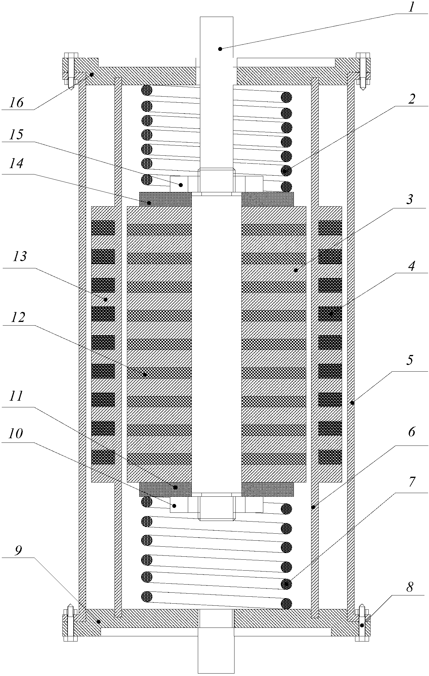
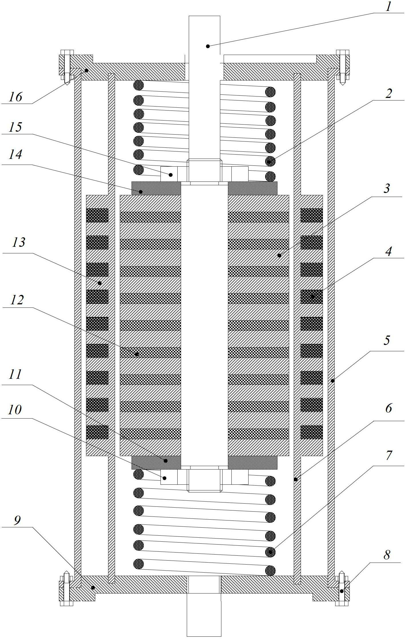
[0021] The structural principle and working principle of the present invention will be further described in detail below in conjunction with the accompanying drawings.

[0022] As described in the drawings, a cylindrical electromagnetic damper of the present invention includes a central shaft 1, and n groups of ring-shaped permanent magnet stacks 3 with the same poles are arranged in sequence on the outer wall of the central shaft 1, and the said n is greater than An integer equal to 2, ferromagnetic gaskets 12 are arranged between the annular permanent magnet stacks 3, and the annular permanent magnet stacks 3 pass through the first fastening nut 10 and the second fastening nut 15 along the axial ends of the central axis 1 Locked on the central shaft 1, an outer thin-walled cylinder 5 is arranged outside the annular permanent magnet stack 3, and there is a gap between the outer thin-walled cylinder 5 and the annular permanent magnet stack 3, and the two ends of the outer thin-...


PUM


Abstract

The invention discloses a cylindrical electromagnetic damper which comprises a centre shaft, wherein n groups of annular permanent magnet stacks with opposite same polarities are sequentially arranged along an axial direction on the outer wall of the centre shaft; n is an integer more than or equal to 2; ferromagnetic gaskets are arranged among the annular permanent magnet stacks; the two ends of the annular permanent magnet stacks along the axial direction of the centre shaft are locked on the centre shaft through a first lock nut and a second lock nut; outer thin wall cylinders are arranged outside the annular permanent magnet stacks, and a gap a gap is arranged between the outer thin wall cylinders and the annular permanent magnet stacks, and a first cover body and a second cover body are fixed on the two ends of the outer thin wall cylinders and in the radical direction of the outer wall of the centre shaft. Preferably, inner thin wall cylinders are arranged between the annular permanent magnet stacks and the outer thin wall cylinders, wherein the inner thin wall cylinders are fixed with the two ends of the inner thin wall cylinders and the center shaft; a plurality of lug bosses at equal intervals are arranged on the outer walls of the inner thin wall cylinders in the axial direction, and a magnetic coil is wound among the lug bosses. By adopting the structure of the cylindrical electromagnetic damper disclosed by the invention, higher electromechanical coupling characteristics as well as vibration isolating and buffering characteristics are provided, and the advantages of simple structure, large operation force, convenience for use, low cost and wide application range are achieved.

Description

technical field [0001] The invention relates to a damper, in particular to a cylindrical electromagnetic damper. Background technique [0002] When the mechanical structure is subjected to external loads, it will vibrate. People can use vibration for conveying, screening, crushing, monitoring and diagnosis, etc., which will facilitate many aspects of industry, agriculture, national defense, and people's lives. However, in the fields of high-tech, precision, and cutting-edge technologies, mechanical vibration will cause structural failure, decreased precision, shortened life, and casualties. For example, when the rocket is launched, the impact load may cause structural damage and reduce the launch accuracy; when the car is driving, the rough and uneven road surface will reduce the comfort; the vibration of the instrument will lead to its measurement accuracy, etc. [0003] The damper can increase the damping coefficient of the structure to a certain extent, so it is widely ...

Claims


Application Information

Patent Timeline
Patent Type & Authority Applications(China)
IPC IPC(8): F16F6/00
Inventor 严博张希农罗亚军边鹏飞
Owner XI AN JIAOTONG UNIV
Why Eureka
Try Eureka