
Method for determining short-circuit position of parallel-wound wires of transformer coil

A technology for transformer coils and determination methods, which is applied to instruments, measuring devices, measuring electrical variables, etc., can solve problems such as hidden dangers, carbonization, coil damage, etc., to simplify the work process and time, reduce material costs, and reduce labor intensity. Effect

Inactive Publication Date: 2012-10-03
WOLONG ELECTRIC GRP CO LTD +1
View PDF3 Cites 5 Cited by
  • Summary
  • Abstract
  • Description
  • Claims
  • Application Information

AI Technical Summary

Problems solved by technology

Basically, after a short circuit occurs in the coil, a method of setting the iron core and increasing the current is used to find the short circuit point, so that the wire insulation part of the coil short circuit point is burned to the highest temperature, and the blackest point of the insulation is carbonized. The position of the smoke is used to determine the short-circuit position, the coil is seriously damaged, and it causes carbonization of the turn wire insulation (radial direction, axial insulation, pads) at the short-circuit point, so it cannot be used, and only new insulation pads or wires can be replaced. , or remove the carbonized outer insulation of the wire, re-wrap the insulation, and re-wind the solution. The above method increases the labor intensity and material cost. It takes about one to three days, and at the same time, the safety and reliability of product quality cannot be guaranteed 100%
Although some manufacturers are looking for solutions, but the search is cumbersome and complicated, and the actual on-site usability is poor

Method used


Image

  • Method for determining short-circuit position of parallel-wound wires of transformer coil
  • Method for determining short-circuit position of parallel-wound wires of transformer coil

Examples


Embodiment Construction

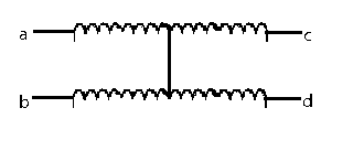
[0015] The technical solution of the present invention will be further described in detail below in conjunction with the accompanying drawings.

[0016] The method for determining the short-circuit position of transformer coils and wires includes the following steps:

[0017] 1) Measure the resistance value RH of the normal wire;

[0018] 2) According to the resistance value of the normal wire, compare the multiple parallel wires in the coil to find the short-circuit wire;

[0019] 3) Use a DC resistance tester to measure the resistance of the short-circuit wire, and connect the first ends of the two short-circuit wires to the DC resistance tester to measure the resistance value Rab of the front section of the wire;

[0020] 4) The resistance value Rab of the front section of the wire is subtracted from the resistance value RB of the wire measured by the DC resistance tester and compared with the resistance value RH of the normal wire to obtain the position of the short-circu...


PUM


Abstract

The invention discloses a method for determining a short-circuit position of parallel-wound wires of a transformer coil and relates to detection of the transformer coil. According to a conventional method for determining the short-circuit position of the parallel-wound wires of the transformer coil, an iron core is sleeved, current is increased, turn wires at a short-circuit point are insulated to cause carbonization, the coil is severely damaged, labor intensity is improved, and material cost is improved. The method provided by the invention comprises the following steps of: 1) measuring, and thus obtaining a resistance value RH of a normal wire; 2) searching a short-circuit wire; 3) measuring, and thus obtaining a front-section resistance value Rab of the wire; 4) subtracting a resistance value RB of a direct current resistance tester measuring line from the front-section resistance value Rab of the wire, comparing a difference value with the resistance value RH of the normal wire, and calculating to determine the position of the short-circuit point; and 5) calculating to determine the short-circuit point between the two wires, and if the quantity of the short-circuit points is more than 1, determining other short-circuit points between the two wires according to the steps 3 and 4 after repairing the short-circuit point. The method is simple, practical and high in efficiency.

Description

technical field [0001] The invention relates to detection of transformer coils. Background technique [0002] The stability and improvement of the manufacturing quality of transformer coils is the main goal of the pursuit and control of the transformer manufacturing industry. The coil is the heart of the transformer and the center of the transformer's power transmission and transformation. To ensure the long-term safe and reliable operation of the transformer, the coil winding process of the transformer must be wound and inspected in accordance with "technical design, process specifications, and quality standards" to ensure the technical parameters of the coil products and the strictness of high quality. . [0003] In the coil winding process, there are various factors affecting product quality, which may occur from raw materials entering the factory to winding, handling, press-fitting, and overall packaging. The short-circuit condition makes it impossible to transfer the...

Claims


Application Information

Patent Timeline
Patent Type & Authority Applications(China)
IPC IPC(8): G01R31/06
Inventor 王汉宁
Owner WOLONG ELECTRIC GRP CO LTD
Learn More