
Monitoring method for ticket checking passage

A channel and ticket checking technology, which is applied to devices that measure the time required to move a certain distance, measuring devices, and re-radiation. Crosstalk between beams and real-time problems, improving accuracy and work efficiency, and the effect of high recognition accuracy

Active Publication Date: 2012-10-03
EASYWAY SUZHOU ELECTRONICS TECH
View PDF6 Cites 11 Cited by
  • Summary
  • Abstract
  • Description
  • Claims
  • Application Information

AI Technical Summary

Problems solved by technology

[0002] The usual area detection light curtain generally contains dozens or even hundreds of infrared emitting and receiving points. The problem of crosstalk between beams, that is, the receiver cannot confirm which emission point the beam comes from; secondly, the existing technology has poor real-time performance. Therefore, how to design a monitoring system that can avoid crosstalk between beams when the distance between infrared emission and receiving units is small method, become the direction of efforts of those of ordinary skill in the art

Method used


Image

  • Monitoring method for ticket checking passage
  • Monitoring method for ticket checking passage

Examples


Embodiment

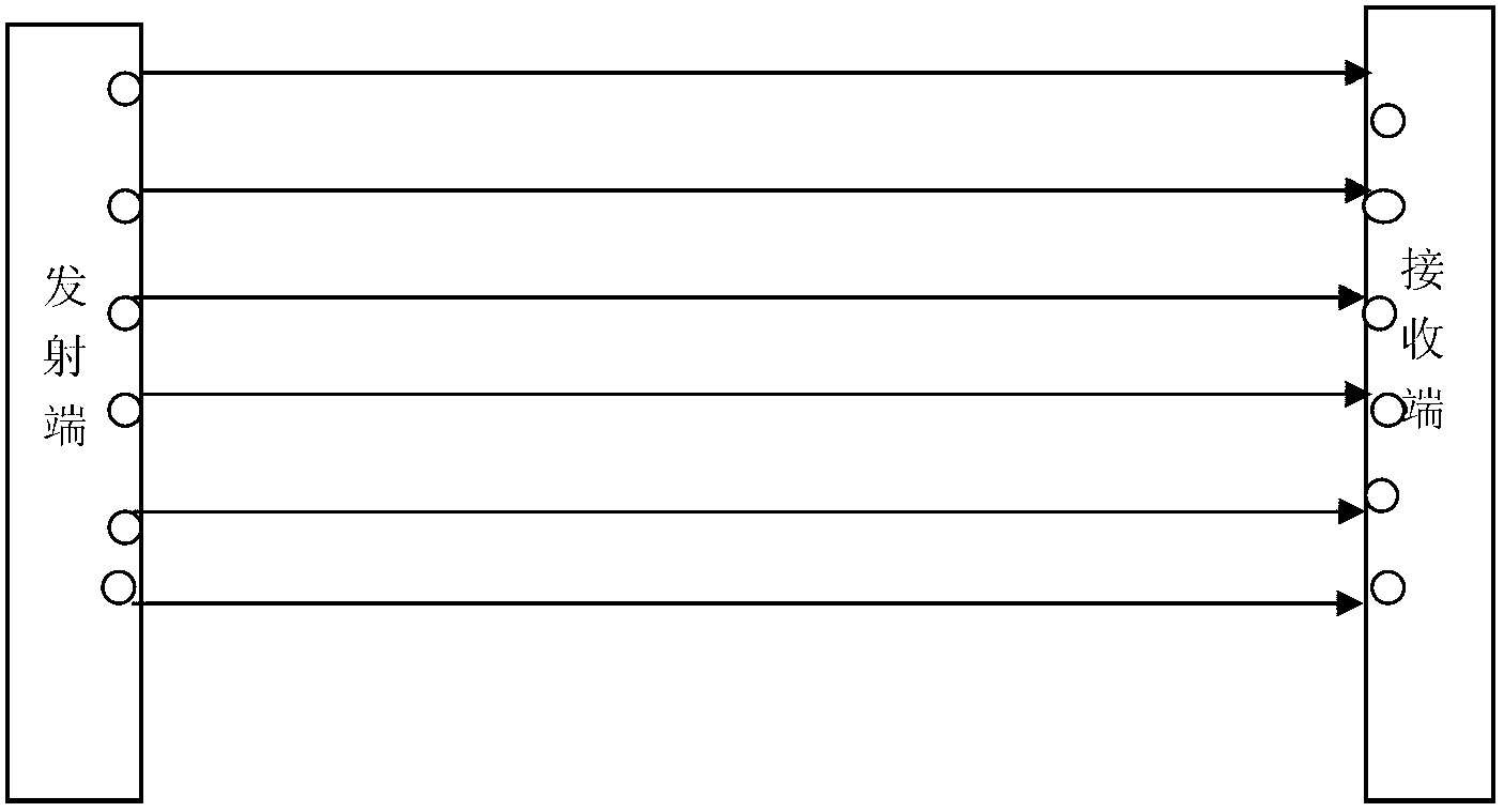
[0021] Embodiment: A monitoring method for a ticket checking channel, the ticket checking channel is mainly composed of a left gate body, a right gate body, a light curtain controller, and several gates installed on the left gate body and the right gate body respectively A transmitting light curtain strip composed of two transmitters and a receiving light curtain strip composed of several receivers, the monitoring method comprises the following steps:

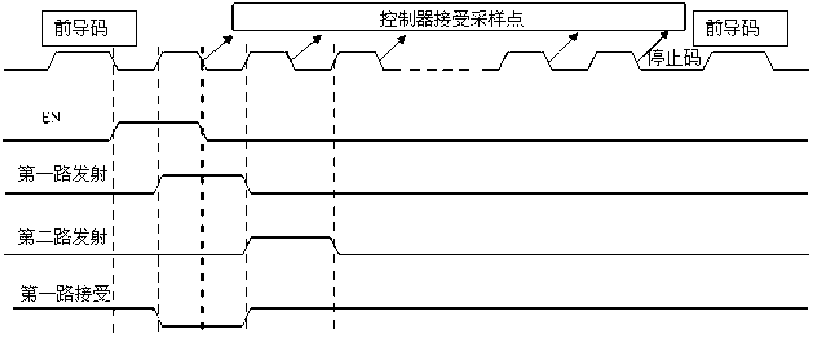
[0022] Step 1. The clock generator in the light curtain controller generates a synchronous continuous square wave signal including several light curtain detection cycles and is used to turn on the emission enable signal emitted by the emitter in the emission light curtain bar and control the received light The control signal received by the receiver in the curtain bar. This synchronous continuous square wave signal is used to synchronize the paired emitting light curtain bar and receiving light curtain bar. In order to start th...


PUM


Abstract

The invention discloses a monitoring method for a ticket checking passage. The monitoring method comprises the following steps of: generating a synchronous continuous square signal and an emission enabling signal which is used for turning on emitters in an emission optical screen strip by a clock generator in an optical screen controller, wherein the synchronous continuous square signal sequentially comprises a front guide code and a detection pulse which is used for controlling a sampling point of the optical screen controller, and at a falling edge of the front guide code, the emission enabling signal is triggered and sustained for the width of one pulse; when the emission enabling signal is positioned at a valid bit, and a detection pulse code is positioned at a rising edge, turning on the emitters positioned at an emission end to allow the emitters to be in an emission state and receivers positioned at a receiving end to allow the receivers to be in a shielding state for one clock period; and when the detection pulse code is positioned at the falling edge, acquiring the working state of each emitter and each receiver by the optical screen controller so as to acquire the shielding position of an object to be monitored at that moment. The monitoring method is high in identification accuracy, and when the separation distance between an infrared emission unit and a receiving unit is small, the problems of crosstalk between light beams and the problem of real-time are solved.

Description

technical field [0001] The invention relates to the field of railway ticket checking, in particular to a monitoring method for a ticket checking channel. Background technique [0002] The usual area detection light curtain generally contains dozens or even hundreds of infrared emitting and receiving points. The problem of crosstalk between beams, that is, the receiver cannot confirm which emission point the beam comes from; secondly, the existing technology has poor real-time performance. Therefore, how to design a monitoring system that can avoid crosstalk between beams when the distance between infrared emission and receiving units is small The method has become the direction of efforts of those of ordinary skill in the art. Contents of the invention [0003] The invention provides a monitoring method for a ticket checking channel. The monitoring method has high recognition accuracy and can ensure that crosstalk between beams is avoided and real-time performance is impr...

Claims


Application Information

Patent Timeline
Patent Type & Authority Applications(China)
IPC IPC(8): G01V8/10G01B11/00G01B11/06G01P3/68
Inventor 翟宁王颖蕊容易
Owner EASYWAY SUZHOU ELECTRONICS TECH
Learn More