Distributed thermal management system for battery modules

A technology of thermal management system and battery module, applied in the direction of secondary battery, battery temperature control, circuit, etc., to achieve long service life and stability, ensure the overall working performance, and ensure the effect of safe use

Active Publication Date: 2012-10-03
山东海量新材料科技有限公司
View PDF12 Cites 47 Cited by
  • Summary
  • Abstract
  • Description
  • Claims
  • Application Information

AI Technical Summary

Problems solved by technology

[0007] However, there is currently no technology that can effectively manage the heat of multiple batteries, and can always ensure that the batteries work at a normal operating temperature regardless of whether the batteries are in a high-temperature or low-temperature environment, thereby ensuring the overall performance of the battery. The battery has a long service life and stability, while ensuring the safe use of the battery

Method used


Image

  • Distributed thermal management system for battery modules
  • Distributed thermal management system for battery modules
  • Distributed thermal management system for battery modules

Examples


Embodiment 1

[0057] Figure 4 It is a schematic structural diagram of Embodiment 1 of a distributed thermal management system for a battery module provided by the present invention when a heating resistor is used for heating operation. At this time, the present invention adopts a solid-state heating method for thermal management.

[0058] see also Figure 4 , for a distributed thermal management system of a battery module provided by the present invention, when using a heating resistor for heating operation, the heating module 200 on each battery module may include a heating resistor 4 and an N-channel MOS switch Tube NMOS, each heating resistor 4 is set on the surface of a battery module;

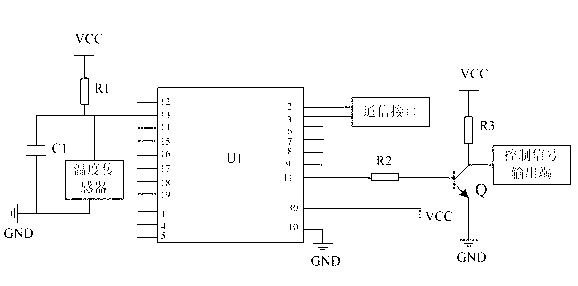
[0059] The gate G of the N-channel MOS switch tube is connected to a control signal output terminal of the single-chip microcomputer U1 (such as figure 2 , image 3 ), the source S of the N-channel MOS switch tube is connected to the heating resistor 4 , and the drain D of the N-channel MOS switch ...

Embodiment 2

[0066] Figure 5 It is a schematic structural diagram of Embodiment 2 of a distributed thermal management system for a battery module provided by the present invention when the air duct is used for heating or cooling operations. At this time, the present invention uses gaseous heating or cooling for thermal management.

[0067] see Figure 5, for a distributed heat management system for battery modules provided in the present invention, when using air ducts for heating or cooling operations, the heating module 200 or the cooling module 300 on each battery module 400 may include The air distribution channel 5 and the valve switch 6, the air distribution channel 5 is formed on the outer wall of the battery module 400, the valve switch 6 is connected to a control signal output terminal of the single chip microcomputer U1 (such as figure 2 , image 3 shown) are connected; the air distribution duct 5 communicates with the top outer wall of the battery module 400, the air divisio...

Embodiment 3

[0073] Image 6 It is a schematic structural diagram of Embodiment 3 of a distributed thermal management system for a battery module provided by the present invention when the liquid channel is used for heating or cooling operations. At this time, the present invention uses a liquid state for heating or cooling thermal management.

[0074] see Image 6 , for a distributed heat management system of a battery module provided in the present invention, when the liquid channel is used for cooling operation, the heating module 200 or cooling module 300 on each battery module 400 may include a flow channel 9 and Valve switch 6, the shunt channel 9 is formed on the outer wall of the battery module 400, the valve switch 6 is connected to a control signal output end of the single chip microcomputer U1 (such as figure 2 , image 3 shown) are connected; the flow channel 9 communicates with the outer wall of the battery module 400, the flow channel 9 communicates with one end of the val...


PUM


Abstract

The invention discloses a distributed thermal management system for battery modules. The system comprises a plurality of battery modules. A thermal management control device is arranged on each battery module. Each thermal management control device comprises at least one temperature detection and control module, at least one heating module and at least one cooling module, wherein the temperature detection and control modules are used for detecting the temperatures of the battery modules in real time, comparing detected temperature values with a preset battery module working temperature value range, and correspondingly starting the heating modules for heating operation or starting the cooling module for cooling operation according to comparison results. According to the distributed thermal management system for the battery modules, thermal management over a plurality of batteries can be effectively realized, and the batteries can be ensured to work at normal working temperature all the time regardless of a high temperature environment or a low temperature environment, so that the overall working performance, long service life and stability of the batteries are ensured.

Description

technical field [0001] The invention relates to the technical field of batteries, in particular to a distributed thermal management system of battery modules. Background technique [0002] At present, lithium-ion batteries have the advantages of high specific energy, many cycle times, and long storage time. They are not only widely used in portable electronic devices such as mobile phones, digital cameras, and laptop computers, but also widely used in electric vehicles and electric bicycles. And large and medium-sized electric equipment such as electric tools. [0003] With the continuous development of lithium-ion battery technology, the specific energy of lithium-ion batteries, battery production materials and battery structure technology have made great progress, making it in the field of power systems, including electric vehicle transportation and energy storage base station communications Lithium-ion batteries are required to provide power, so lithium-ion batteries pl...

Claims


Application Information

Patent Timeline
Patent Type & Authority Applications(China)
IPC IPC(8): H01M10/50H01M10/617H01M10/63
CPCY02E60/12Y02E60/10
Inventor 严玲玲汤曦东刘彩秋张万良
Owner 山东海量新材料科技有限公司
Why Eureka
Try Eureka