
High-voltage power transmission line inspection robot mechanism

A technology for patrolling robots and high-voltage transmission lines, which is applied to manipulators, program-controlled manipulators, overhead lines/cable equipment, etc. Large center of mass adjustment range, strong climbing and moving capabilities, and the effect of reducing mass

Inactive Publication Date: 2012-10-03
NORTHEASTERN UNIV
View PDF6 Cites 40 Cited by
  • Summary
  • Abstract
  • Description
  • Claims
  • Application Information

AI Technical Summary

Problems solved by technology

At present, the robot mechanism of ultra-high voltage transmission lines mainly includes the Canadian Linescout line inspection robot, which cannot realize the turning function; the Japanese Expliner line inspection robot, which cannot change the span, and there is a problem of lateral deviation of the center of mass in the process of adjusting the center of mass; The Chinese patent application number 200410010531.5 discloses a wheel-arm composite inspection robot structure. The mechanism cannot change the span, and the centroid adjustment function is realized by moving the position of the box body; An ultra-high voltage transmission line inspection robot mechanism, the mechanism can only walk along a straight line and cross obstacles, and cannot turn horizontally, and three arms need to work together in the process of crossing obstacles, the mechanism structure is relatively complicated

Method used


Image

  • High-voltage power transmission line inspection robot mechanism
  • High-voltage power transmission line inspection robot mechanism
  • High-voltage power transmission line inspection robot mechanism

Examples


Embodiment Construction

[0022] The present invention will be further described below in conjunction with the accompanying drawings and embodiments.

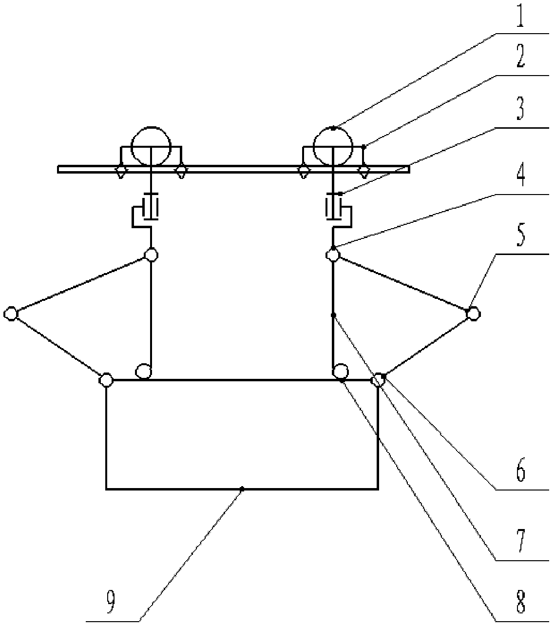
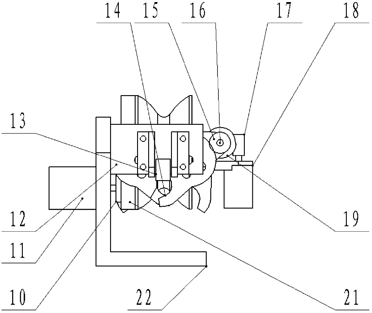
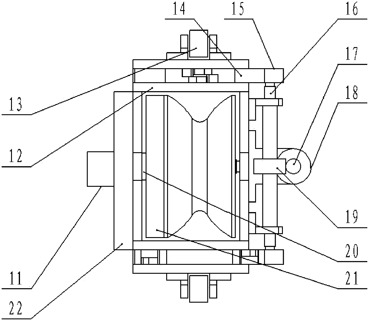
[0023] Such as figure 1 As shown, the high-voltage transmission line inspection robot mechanism of the present invention includes a front claw, a front arm, a center of mass adjustment structure, a rear arm and a rear claw, and the front claw and the rear claw are respectively connected to the ends of the front arm and the rear arm, and Gripping with the line, the claw is a combined structure of a gear pair and a worm gear. The two arms have the same structure, including a horizontal rotation pair 3 and three vertical rotation pairs 4, 5, 6. The center of mass adjustment structure includes a box 9 , roller moving platform 8 and soft cable 7, the two ends on the upper surface of the box body 9 are respectively connected to the third vertical rotation pair 6 of the front arm and the front end of the rear arm, and the two roller moving platforms 8 are symm...


PUM


Abstract

The invention discloses a high-voltage power transmission line inspection robot mechanism, which comprises front paws, a front arm, a mass center adjustment structure, a rear arm and rear paws, wherein the front paws and the rear paws are respectively connected to the tail ends of the front arm and the rear arm and clamped with a power transmission line; the paws comprise gear pairs and worm wheel and worm combined structures; the structures of the two arms are the same, and each of the two arms comprises a horizontal rotation pair and three vertical rotation pairs; the mass center adjustment structure comprises a box body, rotary drum moving platforms and flexible ropes; two ends of the upper surface of the box body are respectively connected with the vertical rotation pairs at the front ends of the front arm and the rear arm; the two rotary drum moving platforms are symmetrically arranged on the box body; one end of each flexible rope is connected with the vertical rotation pair at the rear of each arm; and the other end of each flexible rope is wound on each rotary drum of the mass center adjustment structure. The mechanism is compact in structure; due to a pressing wheel structure, the mechanism can automatically adapt to an angle of the line; when the line is suspended on one arm, the flexible ropes are used for bearing the weight of a robot, so that the requirement on the rigidity of the arms is reduced, and the mass of the arm part of the robot can be effectively reduced; and the mass center is easy to adjust.

Description

technical field [0001] The invention relates to a mobile robot mechanism for overhead lines, in particular to a high-voltage transmission line inspection robot mechanism for safety inspection of high-voltage transmission lines. Background technique [0002] The main method of long-distance power transmission and distribution is to use high-voltage transmission lines. Power equipment exposed to the wild for a long time is prone to damage. If it is not repaired and replaced in time, the original small damage may expand, resulting in interruption of power transmission or even a power transmission accident. Therefore, power transmission Lines need to be checked periodically. The existing line inspection methods mainly include manual inspection and helicopter inspection. Manual inspection is low in efficiency and labor-intensive; helicopter inspection is costly and is greatly restricted by weather conditions. In view of the above reasons, it is of great engineering practical sig...

Claims


Application Information

Patent Timeline
IPC IPC(8): H02G1/02B25J9/06B25J15/00
Inventor 房立金魏永乐陶广宏
Owner NORTHEASTERN UNIV
Learn More