Impulse current inhibiting circuit and supply circuit

A technology of inrush current and power supply circuit, which is applied in the field of circuits and can solve problems such as inrush current

Active Publication Date: 2012-10-03
INVENTRONICS HANGZHOU
View PDF4 Cites 7 Cited by
  • Summary
  • Abstract
  • Description
  • Claims
  • Application Information

AI Technical Summary

Problems solved by technology

[0005] In view of this, the technical problem to be solved in this application is to provide a circuit and power supply circuit for suppressing inrush current, which can solve the problem of instantaneous discharge of the voltage on the output capacitor during the process of switching the constant current source from the no-load state to the load state. The inrush current problem

Method used


Image

  • Impulse current inhibiting circuit and supply circuit
  • Impulse current inhibiting circuit and supply circuit
  • Impulse current inhibiting circuit and supply circuit

Examples


Embodiment Construction

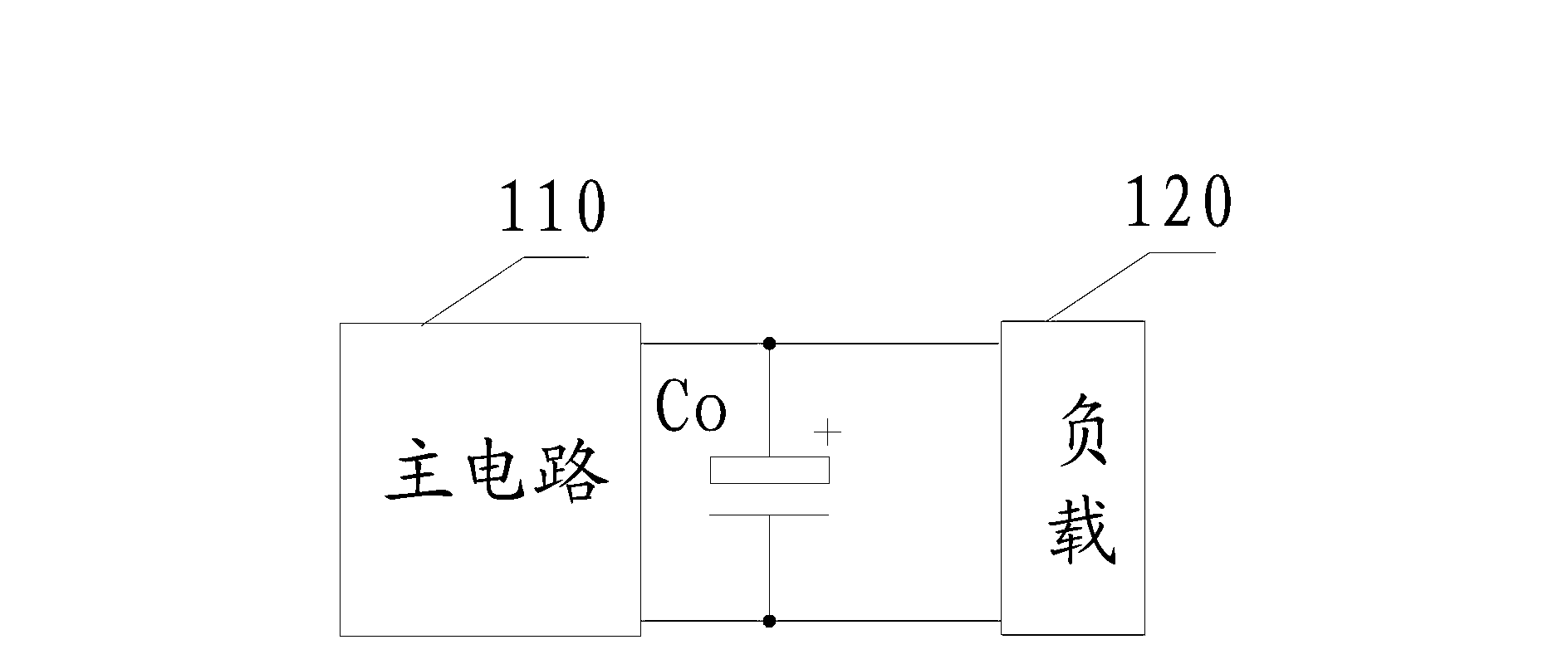
[0048] The circuit for suppressing inrush current described in this application can be applied to figure 1In the power supply circuit shown, the main circuit 110 of the constant current source and the output capacitor Co are part of the constant current source, whether the constant current source includes other structures, and the realization structure of the main circuit of the constant current source are not limited here. In this application, among the input terminals of the load, the input terminal connected to the positive phase output terminal of the main circuit is called the positive phase input terminal, and the input terminal connected to the negative phase output terminal of the main circuit is called the negative phase input terminal. The connection here may be a direct connection or an indirect connection through other devices in the circuit such as resistors and switches.

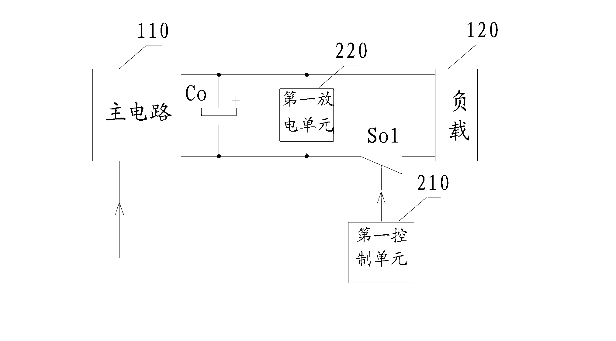
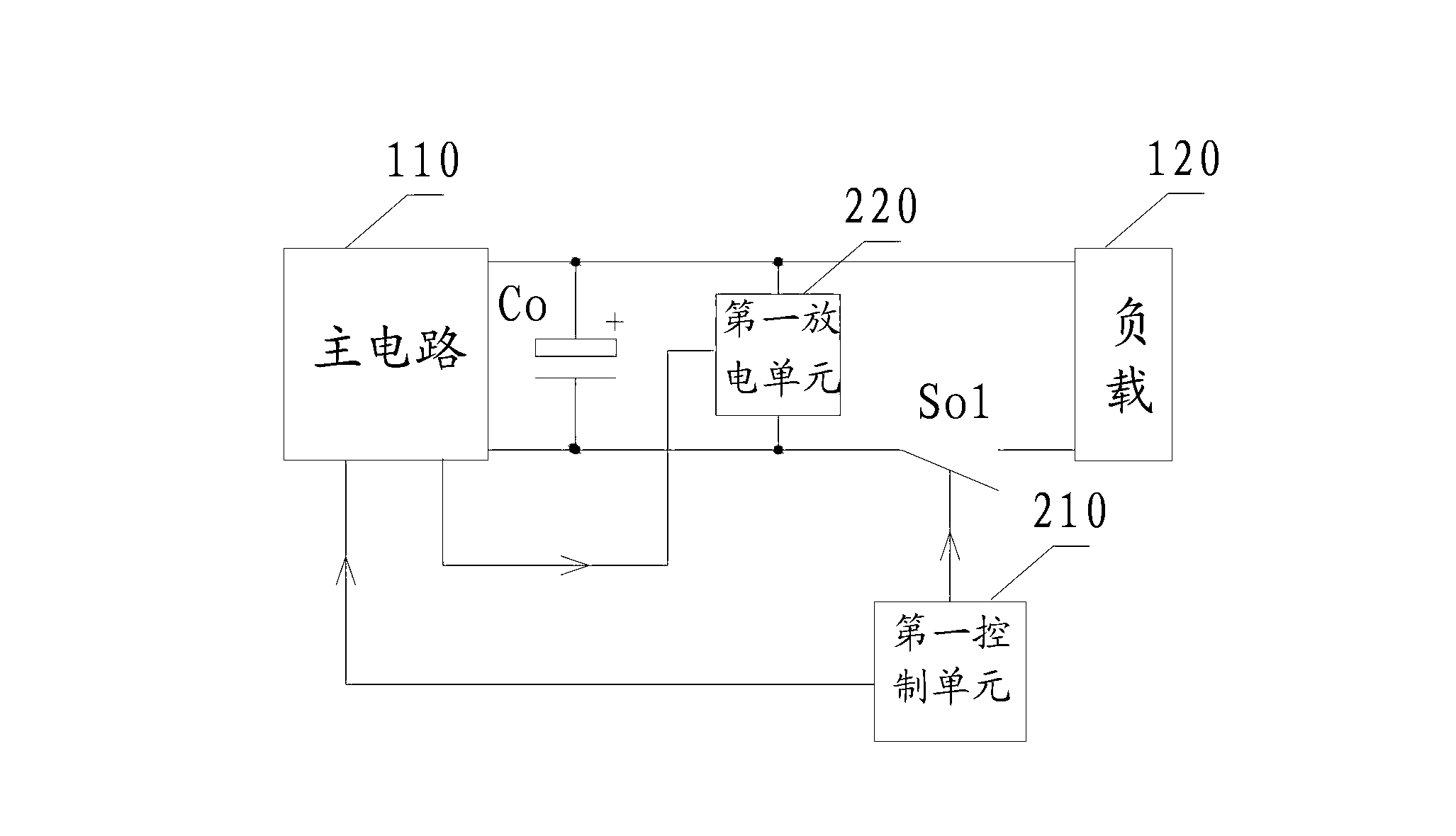
[0049] figure 2 For the first embodiment of the circuit structure for suppressing inrush ...


PUM


Abstract

The invention discloses an impulse current inhibiting circuit and a supply circuit; when a constant current source is transformed into loaded state from unloaded state, a first control unit detects the output current of a main circuit of the constant current source and controls a first output switch to turn off and the main circuit of the constant current source to shutdown when the output current is no less than a predetermined current threshold value; a first discharge unit detects the predetermined parameter of the circuit and discharges an output capacitor when the predetermined parameter satisfies the discharge condition, namely the first discharge unit discharges the output capacitor when the impulse current exists in the supply circuit; the constant current source re-starts again at loaded state when the charge on the output capacitor is discharged to a certain degree, the voltage on the output capacitor slowly increases from a lower set value without occurring the impulse current. According to the technical scheme, the impulse current problem caused by the voltage instantaneous discharge on the output capacitor in the transformation process of the constant current source from unloaded state to loaded state is solved.

Description

technical field [0001] The present application relates to the field of circuits, in particular to a circuit for suppressing surge current and a power supply circuit. Background technique [0002] A switching power supply with constant current output is also called a constant current source. The constant current source can work in the no-load state or in the load state. [0003] The circuit structure when the constant current source is loaded is as follows: figure 1 As shown, a main circuit 110 including a constant current source, an output capacitor Co connected in series between the two output terminals of the main circuit, and a load 120; [0004] In general, the output voltage of the constant current source when it is working with no load is higher than the voltage of the load carried by the constant current source. exist figure 1 In the circuit shown, when the constant current source switches from the no-load state to the load state, since the voltage on the output c...

Claims


Application Information

Patent Timeline
Patent Type & Authority Applications(China)
IPC IPC(8): H02H3/08H02H3/06
Inventor 罗世伟任丽君
Owner INVENTRONICS HANGZHOU
Why Eureka
Try Eureka