
Submersible pump stage

A technology of submersible pumps and pump stages, which is applied in the direction of pumps, pump devices, pump components, etc., and can solve the problems of electric motor breakdown, increased friction, impeller cover plate grinding and wear, etc.

Inactive Publication Date: 2012-10-03
PRAD RES & DEV LTD
View PDF8 Cites 0 Cited by
  • Summary
  • Abstract
  • Description
  • Claims
  • Application Information

AI Technical Summary

Problems solved by technology

The disadvantage of said device is that as solid particles accumulate in the front pocket, said solid particles cause a considerable increase in friction between the rotating parts of the submersible pump stages, which can lead to a breakdown of the electric motor and damage all The cover plate of the impeller described above causes a high degree of abrasive wear

Method used


Image

  • Submersible pump stage
  • Submersible pump stage

Examples


Embodiment Construction

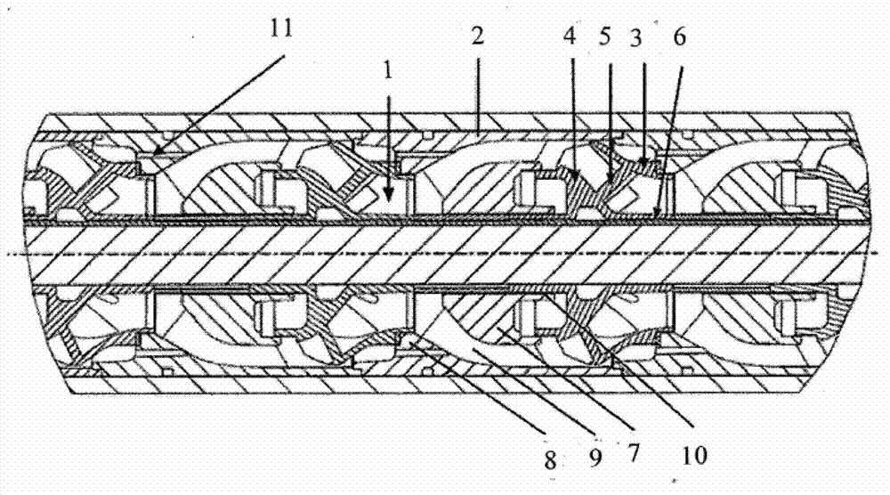
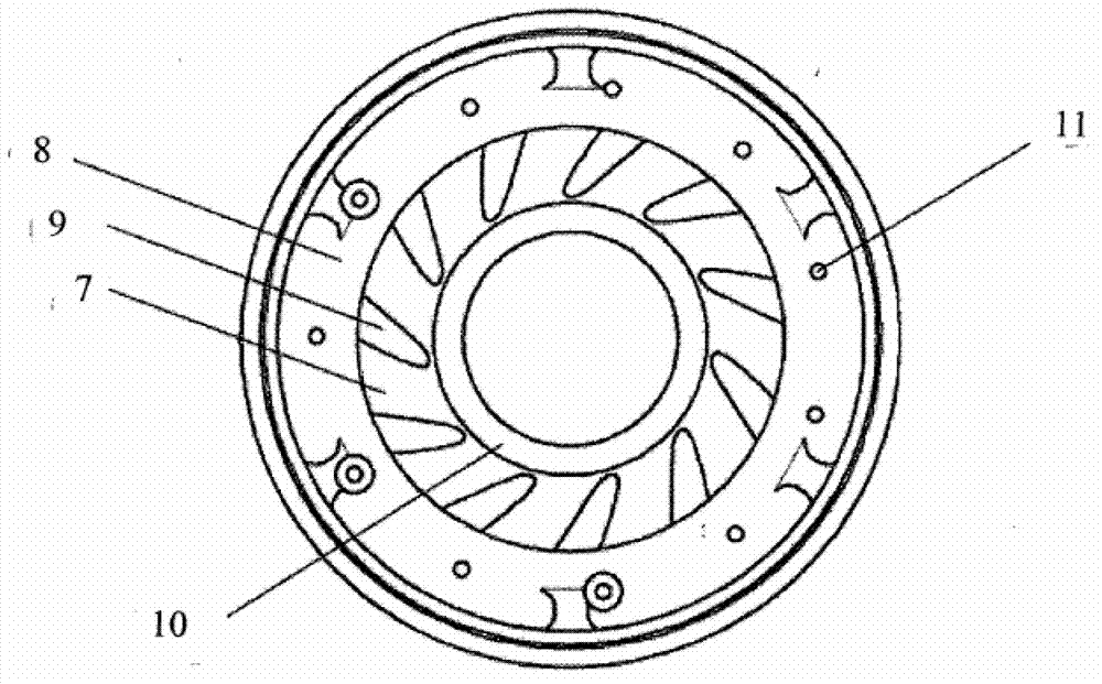
[0014] In order to avoid the collapse of the electric motor, it is necessary to ensure that the front bag is continuously forced to flush. One option for the front bladder flush implementation is to configure special "grind" holes that connect the submersible pump stage front bladder to the guide of the submersible pump's previous stage. In this case, a recirculation movement of liquid occurs in the front pocket, which does not allow the accumulation of solid particles, and the movement of the liquid through the "grinding" holes transports the solid particles out of the pocket cavity to the previous stage of guidance device, solid particles are conveyed from the guide device to the pump stage inlet again. The suction of liquid through the "grind" holes is ensured by the pressure difference between the front bladder of the current stage and the diffuser of the previous stage. The pressure differential at the "grind" holes is approximately equal to the hydraulic pressure of the...


PUM


Abstract

The submersible pump stage comprises an impeller comprising a front cover disk and a rear cover disk, blades arranged between the front and rear cover disks, a sleeve and a guide apparatus, which comprises a front cover disk and a rear cover disk and blades arranged between the front and rear cover disks. The rear cover disk of the guide apparatus is equipped with through-openings which extend in end surfaces and are arranged circumferentially. The number of through-openings is selected to be at least equal to the number of interblade channels. The openings are formed in such a way that liquid can flow from a front pocket of this submersible pump stage into each interblade channel of the guide apparatus of the previous stage. The use of the claimed device reduces the abrasive wear on the cover disk of the impeller and significantly extends the service life of the electric motor.

Description

technical field [0001] The present invention relates to the field of submersible centrifugal pump stages for pumping liquid media, including liquid media containing petroleum, and which can be used in conjunction with fossil minerals in liquid form, including hydrocarbon products in oil wells ) for mining-related operations. Background technique [0002] Different designs of centrifugal pump stages are known, including, for example, those described in a.c. SU 576438, patents RU 2083880 and SU 125408. [0003] A disadvantage of the known design is the lack of structural elements for preventing the accumulation of solid particles in the cavity between the rotating and stationary working surfaces. [0004] The invention most similar to the present invention is the submersible pump stage described in patent RU 68613, said submersible pump stage comprising an impeller comprising a front cover and a rear cover, arranged between said front cover and The blades and sleeves between...

Claims


Application Information

Patent Timeline
Patent Type & Authority Applications(China)
IPC IPC(8): F04D13/10F04D7/02F04D29/44
CPCF04D29/445F04D29/688F04D13/10F04D1/063
Inventor E·M·斯维里多夫A·S·利亚斯科恩A·V·希绍夫J·奥尔班A·P·斯基宾
Owner PRAD RES & DEV LTD
Learn More