Power semiconductor devices having selectively doped JFET regions and related methods of forming such devices

A semiconductor and switching device technology, applied in the field of semiconductor devices with a JFET region, can solve the problems of high-power BJT, large base current, slow BJT switching speed, etc.

Active Publication Date: 2012-10-03
CREE INC
View PDF5 Cites 15 Cited by
  • Summary
  • Abstract
  • Description
  • Claims
  • Application Information

AI Technical Summary

Problems solved by technology

As such, relatively complex external drive circuits may be required to provide the relatively large base currents that high power BJTs may req

Method used


Image

  • Power semiconductor devices having selectively doped JFET regions and related methods of forming such devices
  • Power semiconductor devices having selectively doped JFET regions and related methods of forming such devices
  • Power semiconductor devices having selectively doped JFET regions and related methods of forming such devices

Examples


Embodiment Construction

[0028] The invention is described more fully hereinafter with reference to the accompanying drawings, in which embodiments of the invention are shown. However, this invention may be embodied in many different forms and should not be construed as limited to the embodiments set forth herein. Rather, these embodiments are provided so that this disclosure will be thorough and complete, and will fully convey the scope of the invention to those skilled in the art. In the drawings, the size and relative sizes of layers and regions may be exaggerated for clarity. It will be understood that when an element or layer is referred to as being "on," "connected to" or "coupled to" another element or layer, it can be directly on the other element or layer. An element or layer may be on, directly connected to, or coupled to another element or layer, or intervening elements or layers may be present. In contrast, when an element is referred to as being "directly on," "directly connected to" or...


PUM


Abstract

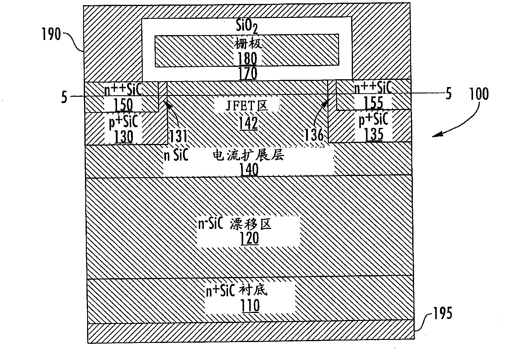
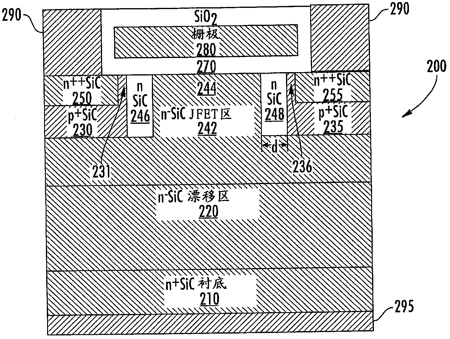
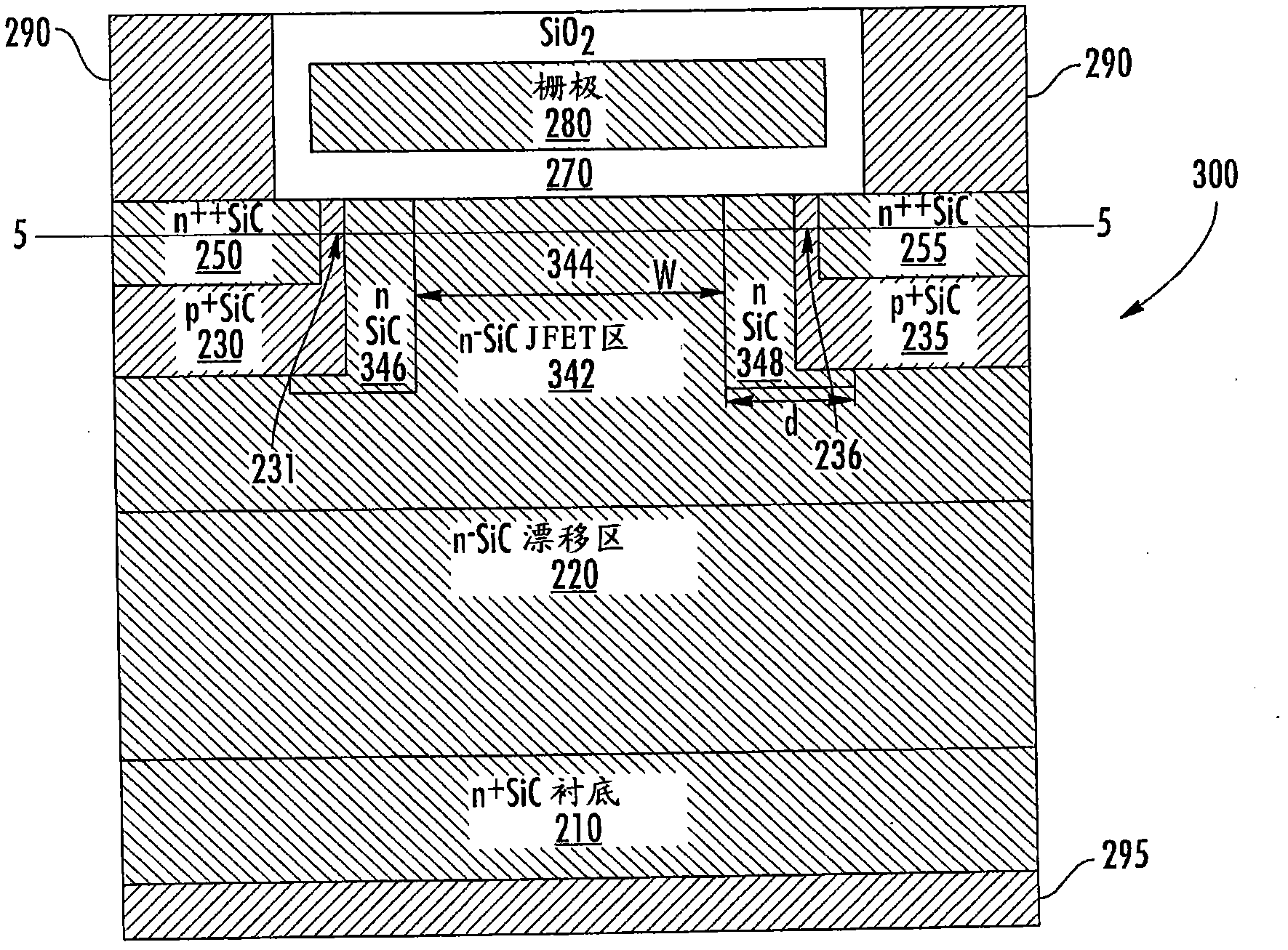
Semiconductor switching devices include a wide band-gap drift layer having a first conductivity type (e.g., n-type), and first and second wide band-gap well regions having a second conductivity type (e.g., p-type) on the wide band-gap drift layer. First and second wide band-gap source/drain regions of the first conductivity type are on the first and second wide band-gap well regions, respectively. A wide band-gap JFET region having the first conductivity type is provided between the first and second well regions. This JFET region includes a first local JFET region that is adjacent a side surface of the first well region and a second local JFET region that is adjacent a side surface of the second well region. The local JFET regions have doping concentrations that exceed a doping concentration of a central portion of the JFET region that is between the first and second local JFET regions of the JFET region.

Description

technical field [0001] The present invention relates to semiconductor devices, and more particularly to semiconductor devices having JFET regions. Background technique [0002] A power metal oxide semiconductor field effect transistor ("MOSFET") is a well-known type of semiconductor transistor that can be used as a switching device in high power applications. A power MOSFET can be turned on or off by applying a gate bias voltage to the gate electrode of the device. When a power MOSFET is turned on (ie it is in its "on state"), current is conducted through the MOSFET's channel. When the bias voltage is removed from the gate electrode (or the bias voltage is lowered below a threshold level), current ceases to conduct through the channel. For example, an n-type MOSFET turns on when a gate bias sufficient to form a conductive n-type inversion layer in the p-type channel region of the device is applied. The n-type inversion layer is electrically connected to the n-type source ...

Claims


Application Information

Patent Timeline
IPC IPC(8): H01L29/80
CPCH01L29/0878H01L29/66068H01L29/7802H01L29/7395H01L29/1608H01L21/326H01L29/772H01L29/80
Inventor 张清纯
Owner CREE INC
Why Eureka
Try Eureka