Flowing electrolyte reservoir system

A technology of flowing electrolyte and electrolyte, which is applied in the direction of transferring electrolyte devices, circuits, fuel cells, etc., and can solve problems such as large system, high pipeline cost, and potential safety hazards

Active Publication Date: 2012-10-03
REDFLOW PTY LTD
View PDF3 Cites 3 Cited by
  • Summary
  • Abstract
  • Description
  • Claims
  • Application Information

AI Technical Summary

Problems solved by technology

However, this conventional shape and arrangement of dielectric storage tanks can lead to a number of problems including: safety hazards associated with leaking electrolyte, prohibitive plumbing costs, wasted material, high manufacturing costs, and oversized systems

Method used


Image

  • Flowing electrolyte reservoir system
  • Flowing electrolyte reservoir system
  • Flowing electrolyte reservoir system

Examples


Embodiment Construction

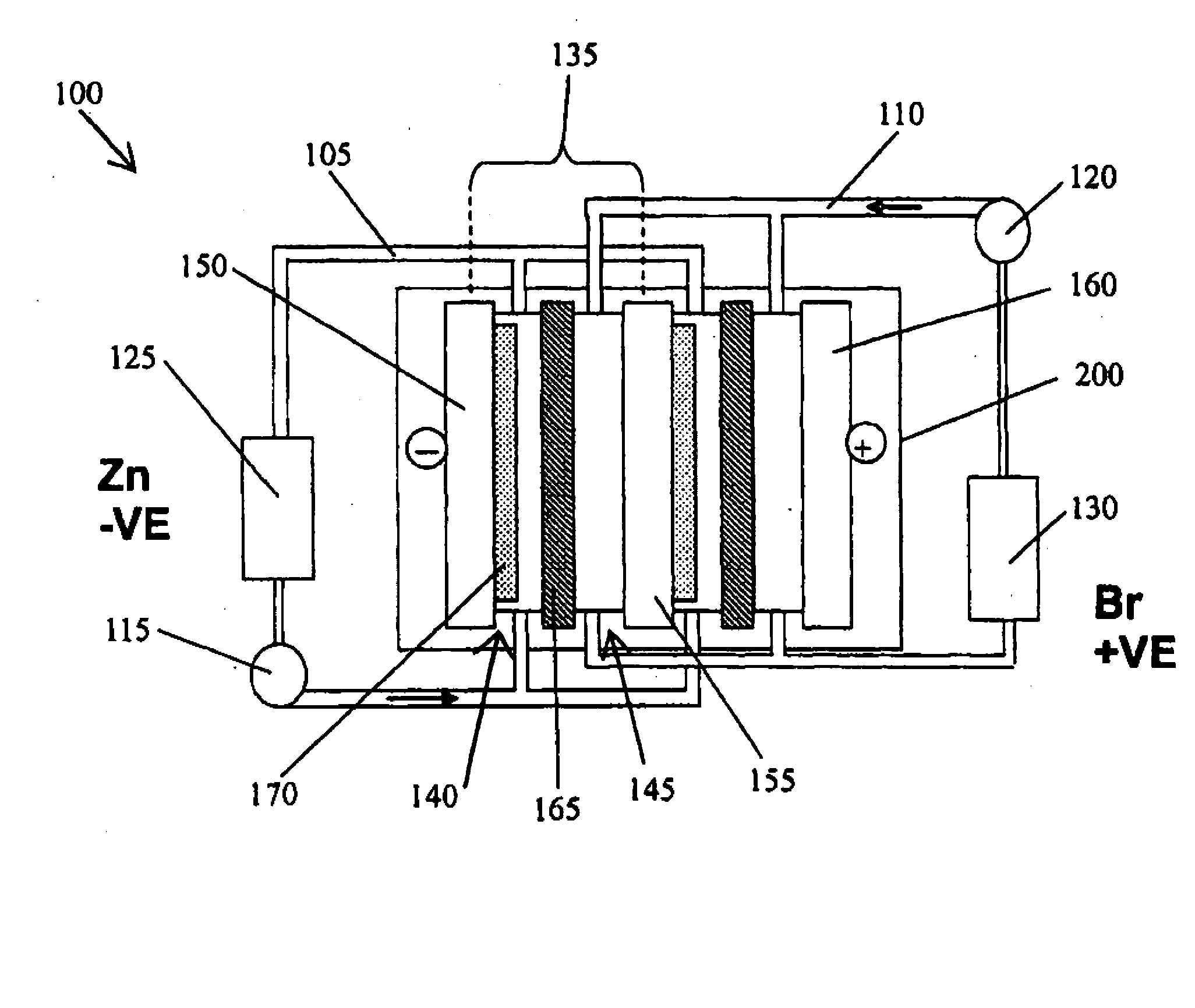
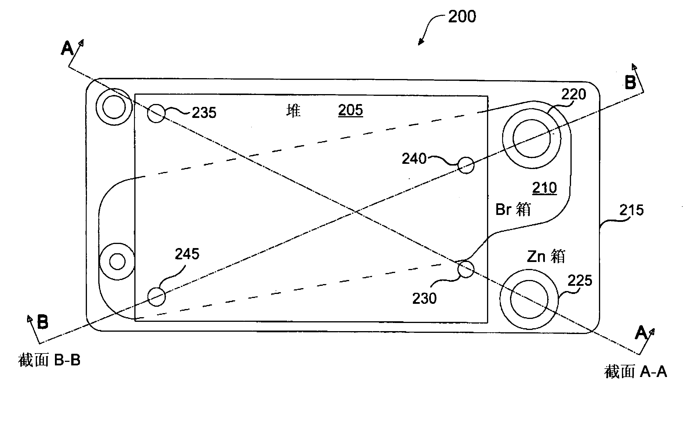
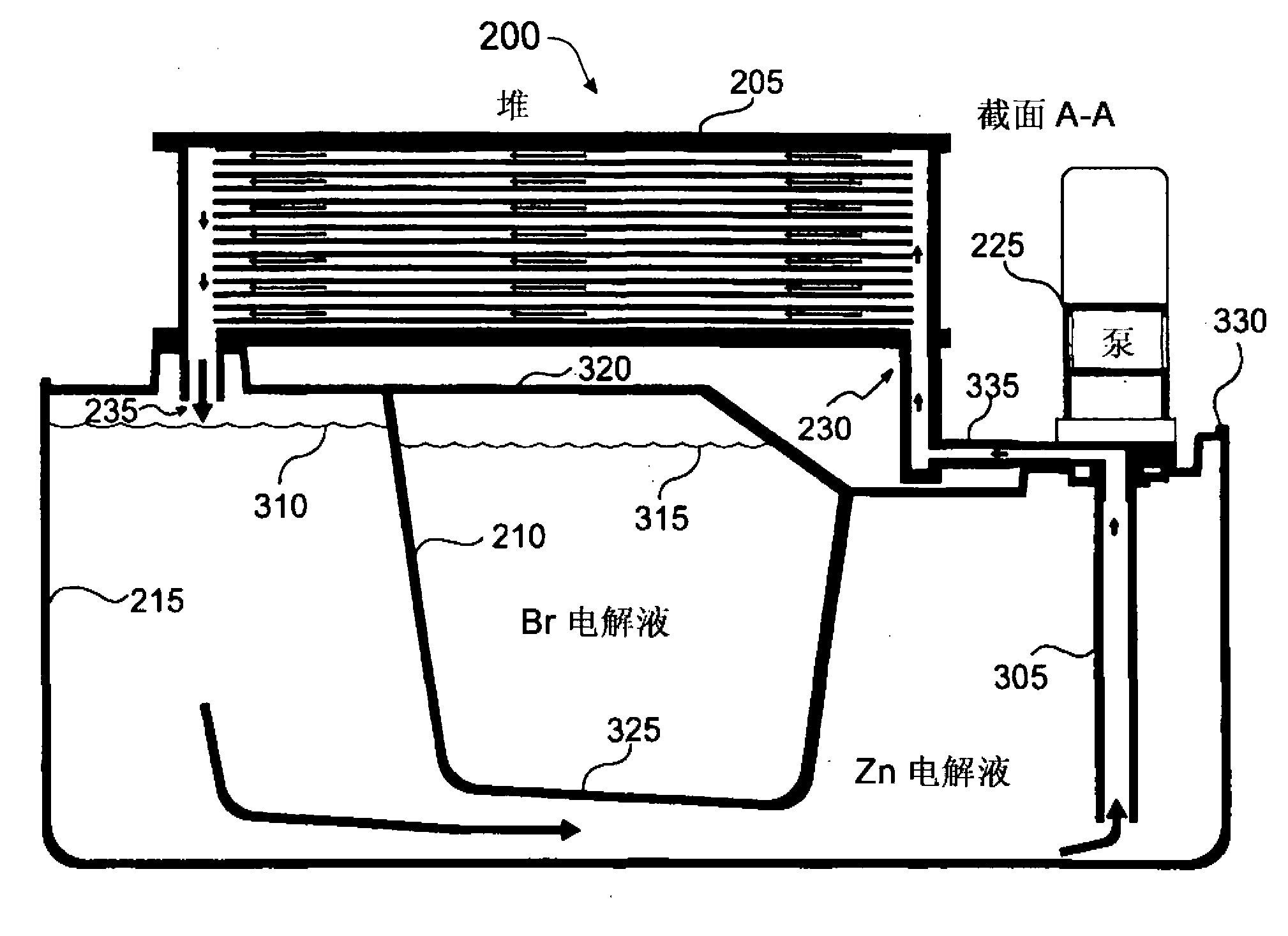
[0043] Embodiments of the invention include battery stacks for flowing electrolyte batteries. Elements of the invention are shown in a simplified form in the drawings so that only those specific details necessary to understand the embodiments of the invention are shown so as to avoid disclosing details that would be apparent to those skilled in the art from the description. Extra details mixed in.

[0044] In this patent specification, adjectives such as first and second, left and right, front and rear, upper and lower are only used to distinguish and define one element or method step from another element or method step, and do not necessarily need to be defined by these Adjectives describe a specific relative position or order. Words such as "comprises" or "comprises" are not used to define an exclusive set of elements or method steps. Rather, these words only define a minimum set of elements or method steps included in a particular embodiment of the invention.

[0045] re...


PUM


Abstract

A flowing electrolyte reservoir system (500) for a flowing electrolyte battery. The system (500) comprises an outer electrolyte tank (515) and an inner electrolyte tank (510) placed under a battery cell stack (640). The inner tank (510) is transversely positioned between opposite corners of the outer electrolyte tank (515), and beneath opposite corners of the battery cell stack (640).

Description

technical field [0001] The present invention relates to flowing electrolyte batteries. The present invention relates particularly, but not exclusively, to a mobile electrolyte storage system having a tank within a tank. Background technique [0002] The battery packs used in stand-alone power systems are usually lead-acid battery packs. However, lead-acid battery packs have limitations in terms of performance and environmental safety. For example, typical lead-acid batteries often have a very short life when exposed to hot climates, especially when they are occasionally fully discharged. Lead-acid batteries are also harmful to the environment because lead is a major component of lead-acid batteries and can cause serious environmental problems during manufacture and disposal. [0003] Flow electrolyte batteries, such as zinc-bromine batteries, zinc-chloride batteries, and vanadium flow batteries, offer the potential to overcome the aforementioned limitations of lead-acid b...

Claims


Application Information

Patent Timeline
Patent Type & Authority Applications(China)
IPC IPC(8): H01M2/36H01M2/38H01M10/04H01M10/02H01M50/77
CPCH01M8/20Y02E60/528H01M8/188H01M10/365Y02E60/50Y02E60/10H01M50/77Y02P70/50
Inventor A·R·温特
Owner REDFLOW PTY LTD
Why Eureka
Try Eureka