Aerodynamic loading system and loading method for undercarriage self-control spring-damping system

A damping system and load loading technology, which is used in aircraft component testing, aircraft parts, ground devices, etc., can solve the problems of inability to design cam loading requirements, the loading accuracy cannot be guaranteed, and the hydraulic actuator requirements are high, and achieve load simulation. The effect of good continuity, small footprint and wide application

Active Publication Date: 2012-10-10
NANJING UNIV OF AERONAUTICS & ASTRONAUTICS
View PDF5 Cites 18 Cited by
  • Summary
  • Abstract
  • Description
  • Claims
  • Application Information

AI Technical Summary

Problems solved by technology

[0006] The structure of this scheme is relatively simple, and the tracking performance of load simulation is better, but its disadvantage is that it has higher requirements on the hydraulic cylinder
[0008] The aerodynamic load of this scheme is closer to the real situation, and the load direction is good, but its shortcomings are as follows: first, the structural design is more complicated, and the number of wire ropes is too large, which makes it easy to interfere with the landing gear; second, according to the The size of the upper aerodynamic load can only be designed with a unique cam shape corresponding to it, corresponding to some load conditions may not be able to design the corresponding cam to meet its loading requirements; There will be shaking, the loading accuracy cannot be guaranteed, and there are certain safety hazards
[0014] During the retraction process, the horizontal servo motor needs to be reversed twice to ensure that there is always tension on the wire rope. The reverse rotation of the servo motor can cause discontinuous load simulation during the landing gear retraction process, and even cause the wire rope to detach from the steering pulley on the lifting platform.

Method used


Image

  • Aerodynamic loading system and loading method for undercarriage self-control spring-damping system
  • Aerodynamic loading system and loading method for undercarriage self-control spring-damping system
  • Aerodynamic loading system and loading method for undercarriage self-control spring-damping system

Examples


Embodiment Construction

[0041] The present invention will be further elaborated below in conjunction with the accompanying drawings and specific examples of implementation. It should be understood that these examples of implementation are only used to further illustrate the present invention, and are not intended to limit the scope of the present invention. After reading the present invention, those skilled in the art will understand this Modifications of various equivalent forms of the invention all fall within the scope defined by the appended claims of the present application.

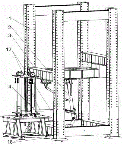
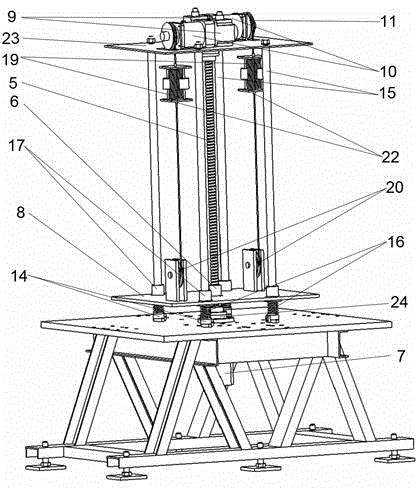
[0042] Such as figure 1 and figure 2 As shown, a self-controlled spring-damping system aerodynamic load loading scheme, which includes: test bench 1, aircraft landing gear 2, strut actuator 3, support frame 4, the load following device includes The ball screw 5, the ball screw nut 6, the lifting table servo motor 7, the lifting table 8, the fixed pulley 20, the angle sensor 24, the lifting table 4 are fixedly installed o...


PUM


Abstract

The invention discloses an aerodynamic loading system and a loading method for aero-undercarriage self-control spring-damping system and belongs to aero-undercarriage control test systems. The aerodynamic loading system comprises a test rack (1), an aero-undercarriage (2), a strutting actuator (3) and a support frame (4), wherein the strutting actuator (3) and the support frame (4) are connected on the aero-undercarriage (2), an aerodynamic loading direction control mechanism controls the direction of aerodynamic load during undercarriage control, and an aerodynamic loading size simulation mechanism controls the size of the aerodynamic load during the undercarriage control. The aerodynamic loading system and the loading method for the self-control spring-damping system is high in loading accuracy, good in loading simulation continuity, concise in structure and applicable to tests of undercarriage control of various planes and can provide corresponding accurate parameters for design and development of aero-undercarriages.

Description

technical field [0001] The invention relates to an aerodynamic load loading system and a loading method of an automatic control spring-damping system of a landing gear, belonging to an aircraft landing gear retractable test system. Background technique [0002] In order to ensure the aerodynamic shape of the aircraft during flight, modern aircraft are generally designed with retractable landing gear. When flying in the air, the landing gear is retracted inside the fuselage or wing; the landing gear is lowered during take-off and landing. Withstand ground loads. Therefore, when the aircraft is flying in the air, it is necessary to complete the retracting and lowering actions of the landing gear. Due to the influence of air resistance, the landing gear will be affected by the aerodynamic force when retracting and retracting. The aerodynamic force is distributed on the windward surface of the landing gear, which affects the work of the landing gear strut actuator and the u...

Claims


Application Information

Patent Timeline
Patent Type & Authority Applications(China)
IPC IPC(8): B64F5/00B64F5/60
Inventor 聂宏孙稳魏小辉杜楠楠房务官王钰龙
Owner NANJING UNIV OF AERONAUTICS & ASTRONAUTICS
Why Eureka
Try Eureka