Eureka AIR delivers breakthrough ideas for toughest innovation challenges, trusted by R&D personnel around the world.

System and method for laser flatness measurement

A flatness and plane technology, applied in the field of laser plane measurement system, can solve the problems of low efficiency and slow detection speed, and achieve the effect of convenient replacement of workpieces, improvement of efficiency, and convenient product positioning

Inactive Publication Date: 2012-10-10
HONG FU JIN PRECISION IND (SHENZHEN) CO LTD +1
View PDF6 Cites 10 Cited by
  • Summary
  • Abstract
  • Description
  • Claims
  • Application Information

AI Technical Summary

Problems solved by technology

[0002] Due to the high pursuit of product appearance quality in modern life, the production process of the product will be very strict. When the shape of a certain plane of the product is relatively strict, it is necessary to do a flatness test on this plane, and the current flatness routine The detection method is one by one detection, the detection speed is slow and the efficiency is low

Method used


Image

  • System and method for laser flatness measurement
  • System and method for laser flatness measurement
  • System and method for laser flatness measurement

Examples


Embodiment Construction

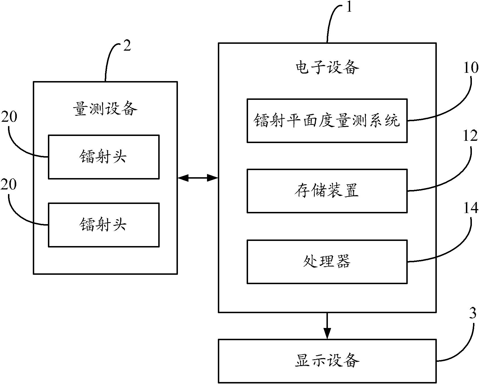
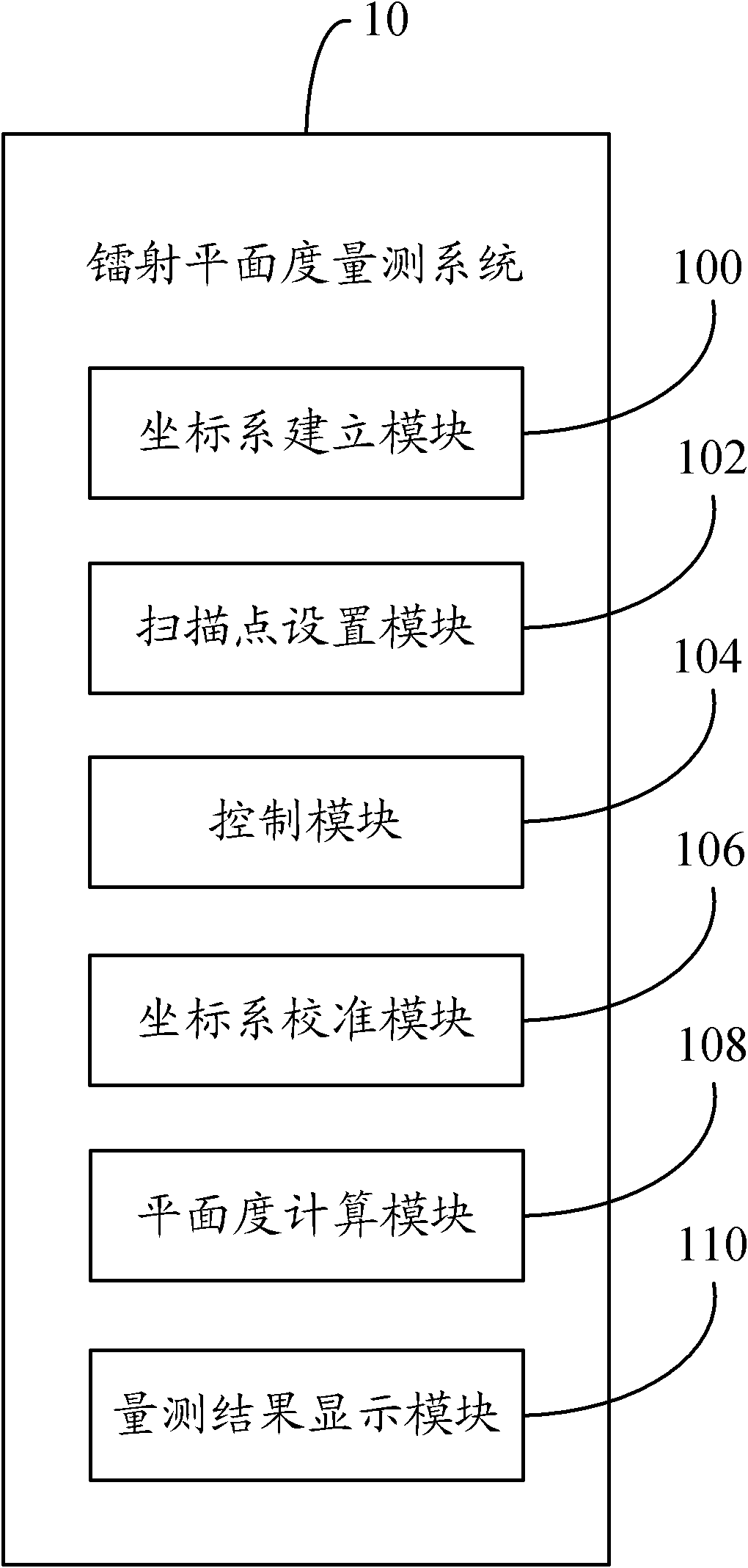
[0016] refer to figure 1 As shown, it is a schematic diagram of the operating environment of the preferred embodiment of the laser plane metrology system of the present invention. The laser plane measuring system 10 runs in an electronic device 1 (such as a computer), and the electronic device 1 is connected with a measuring device 2, and the measuring device 2 has two laser heads 20 and a workbench , the user can clamp the jig with the workpiece on the workbench before the laser head 20 measures the workpiece. In this embodiment, two workpieces can be installed on the jig at the same time, and the two laser heads 20 are respectively located above the two workpieces for scanning the two workpieces to measure the two workpieces. For example, the laser head 20 includes a and b, and the two workpieces installed on the fixture are c and d respectively, wherein, a is located above c, b is located above d, a is used to scan c, and b is used to scan d .

[0017] In this embodiment...


PUM


Abstract

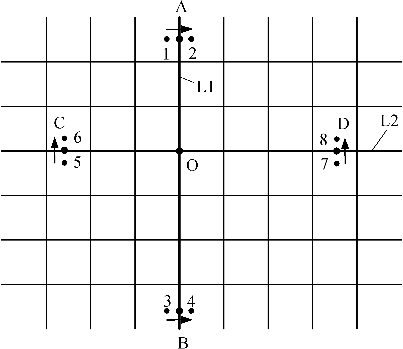
A method for laser flatness measurement comprises that: a tool needed for measuring workpieces is clamped onto a workbench of measurement equipment and fixed. A coordinate system is established, wherein the measurement equipment is provided with two laser heads. Two sets of scanning points are arranged along a horizontal direction and a vertical direction, and each set of scanning points comprises a start point and an end point. The workbench of the measurement equipment is separately moved to the each set of scanning points. The two laser heads are controlled to scan from the start point to the end point, and X, Y and Z axis coordinate values of the each scanning point is record. The coordinate system is corrected according to the X, Y and Z axis coordinate values of the each scanning point. The two workpieces are separately measured by controlling the laser heads. The flatness of each workpiece is calculated according to the corrected coordinate system and measurement data, and is determined whether to be qualified or not based on a predetermined range and a determined result is reminded. The invention further provides a system for the laser flatness measurement. The efficiency of measurement can be improved by applying the method and the system.

Description

technical field [0001] The invention relates to an image measurement system and method, in particular to a laser plane measurement system and method. Background technique [0002] Due to the high pursuit of product appearance quality in modern life, the production process of the product will be very strict. When the shape of a certain plane of the product is relatively strict, it is necessary to do a flatness test on this plane, and the current flatness routine The detection method is to detect one by one, and the detection speed is slow and the efficiency is low. Contents of the invention [0003] In view of the above, it is necessary to propose a laser plane measurement method that can measure two products at the same time and improve the efficiency of the same product measurement operation. [0004] In view of the above, it is also necessary to propose a laser plane measurement system that can measure two products at the same time and improve the efficiency of the same...

Claims


Application Information

Patent Timeline
Patent Type & Authority Applications(China)
IPC IPC(8): G01B11/30
CPCG01B11/306
Inventor 张旨光袁忠奎蒋理薛晓光
Owner HONG FU JIN PRECISION IND (SHENZHEN) CO LTD
Why Eureka
Eureka Blog
Learn More