Air bag die and method for machining air bag by adopting same

An airbag and mold technology, applied in the field of molds, can solve the problems of high labor intensity for mold users, lower airbag production efficiency, and increased labor intensity for operators, so as to improve appearance and quality, increase manufacturing yield, and reduce procedures Effect

Active Publication Date: 2012-10-17
NFC SHENYANG PUMP IND
View PDF2 Cites 11 Cited by
  • Summary
  • Abstract
  • Description
  • Claims
  • Application Information

AI Technical Summary

Problems solved by technology

[0012] The mold disadvantages of this structure are: (1) The mold manufacturing is complicated
[0013] (2) The molding process is cumbersome
[0014] (3) Rubber burrs are easily formed at the part of the mold split core, which affects the appearance and quality of the product
And during the vulcanization process, the airtightness of the airbag mold is reduced, and the vulcanization pressure is reduced by dividing the core, so that the density of the airbag is reduced
[0015] (4) Airbag molding effects are uneven
Because the airbag mold has been used for a long time, assembled repeatedly, and after repeated thermal expansion and contraction, the assembly surface of the split core component and other assembly surfaces may not fit as required. At this time, the operator still uses the same amount of rubber Casting; after the rubber is heated by the vulcanizer into glue, the glue will flow into each deformed assembly surface, resulting in insufficient airbag glue volume and uneven wall thickness, which directly affects the inner quality of the airbag and reduces the service life of the airbag
[0016] (5) Unable to detect the inner quality of the airbag
Manufacturing defects such as uneven wall thickness, shrinkage cavities, and shrinkage porosity generated during the production process of the airbag cannot be detected
[0017] (6) The production efficiency of the product is low, and the labor intensity of the mold user is relatively high
Since the split core assembly needs to be disassembled repeatedly during the airbag manufacturing process, the operator needs to tighten and loosen the same bolt 40 times when making an airbag, and each solid split core itself has a weight of about 40kg , all of which increase the labor intensity of the operator invisibly, thus reducing the efficiency of airbag production

Method used


Image

  • Air bag die and method for machining air bag by adopting same
  • Air bag die and method for machining air bag by adopting same
  • Air bag die and method for machining air bag by adopting same

Examples


Embodiment Construction

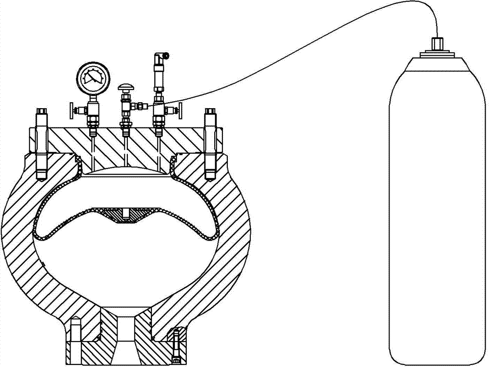
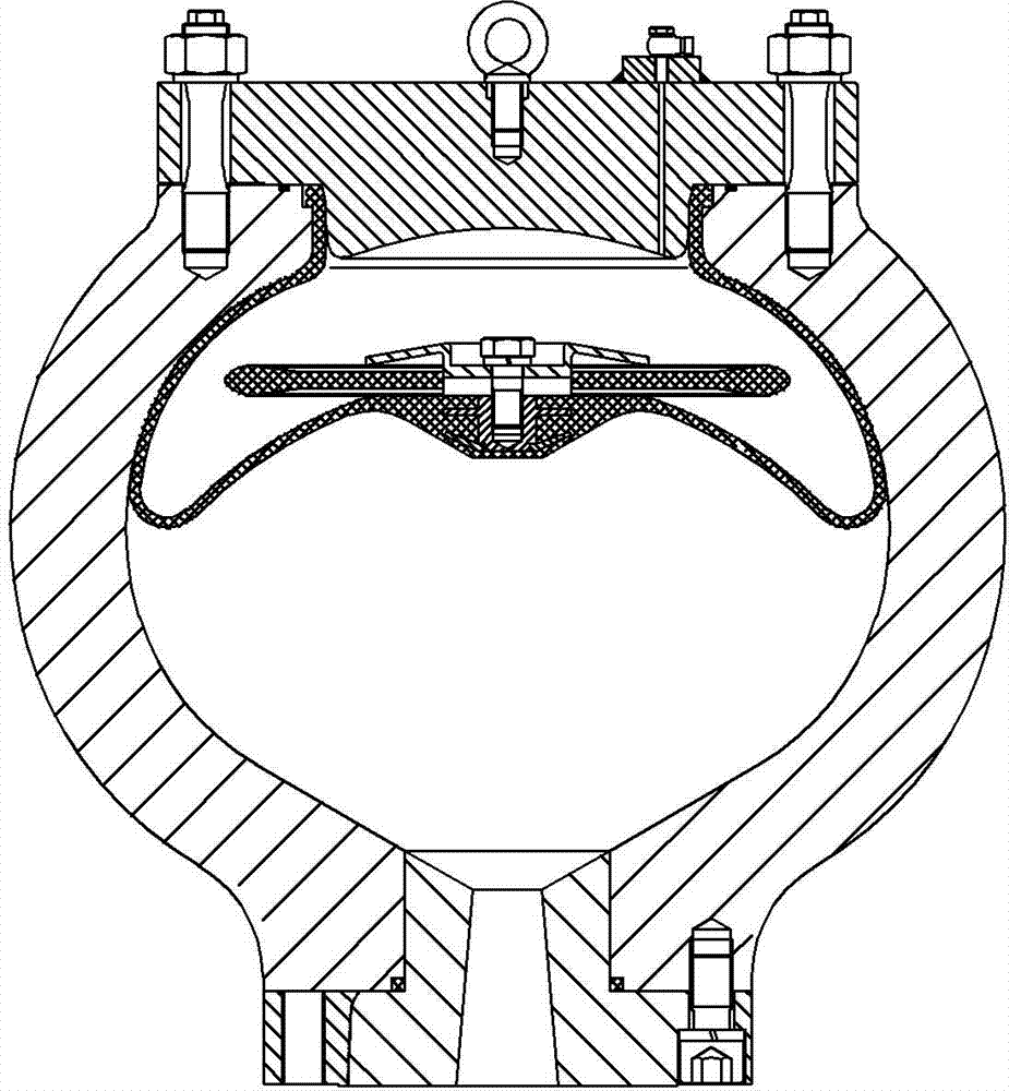
[0058] The airbag mold of the present invention will be described in further detail below in conjunction with the accompanying drawings.

[0059] like Figure 6 and Figure 9 Shown are the structural schematic diagram of the airbag mold of the present invention, and the split view of each part of the airbag mold. The lower mold 12 is located at the bottom of the entire mold, and the middle part of the lower mold 12 has a conical protrusion 13 (arc surface), and a concave center 17 is formed at the top center of the conical protrusion 13. The shape of 16 is corresponding, and airbag iron core 16 is a trapezoidal platform; The wall height of the outer edge of lower mold 12 is slightly lower than the top of circular truncated protrusion 13, and the outer wall top of lower mold 12 has glue flow groove 1.

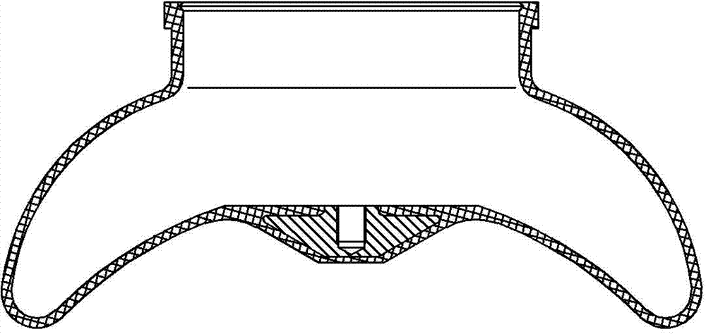
[0060] The top of the lower mold 12 is the central core 10, and the central core 10 is buckled upside down on the lower mold 12 like a "bowl". The center core 10 is di...


PUM


Abstract

The invention belongs to the technical field of dies, and in particular relates to an air bag die and a method for machining an air bag by adopting the air bag die. The invention provides an air bag die and method for machining the air bag, which not only can ensure air bag forming rate, and prolong the service life of the air bag, but also can improve the air bag production efficiency. The air bag die consists of a lower die, a middle die and an upper die, wherein a cone frustum-shaped bump is arranged in the middle of the lower die, and an air bag iron core adaptive to the shape of a depressed center at the top of the cone frustum-shaped bump is arranged at the center of the lower die; a middle core is arranged above the lower die, a cylindrical cavity with an upward opening is arranged in the middle of the middle core, and a through hole is arranged at the bottom of the cavity and internally provided with a connecting bolt; the middle die is positioned above the middle core, the upper part of the middle core penetrates through the center of the middle die, and a glue flowing channel is arranged on the outer edge of the lower die corresponding to the bottom of an outer arc surface of the middle core; and the upper die is positioned above the middle die, and a middle jacket is arranged between the inner side wall of the hollow center of the upper die and an annular bushing part at the upper part of the middle core.

Description

technical field [0001] The invention belongs to the technical field of moulds, and in particular relates to a mold for processing an airbag and a method for processing an airbag by using the mold. Background technique [0002] Diaphragm pump is the core equipment for long-distance pipeline transportation of solid-liquid two-phase medium. Its main components include: power transmission system, power end, hydraulic end, hydraulic control system, feed pressure compensation system, discharge pressure compensation system, and electric control system. The pressure compensation system is divided into two forms: pressure compensation tank and nitrogen bag. [0003] Diaphragm pump adopts spherical preloaded nitrogen bag. Its main role is to stabilize pressure and flow. The nitrogen bag is an auxiliary device that uses the compression and expansion of the gas to store or release a part of the liquid to reduce the vibration of the pipeline system and the unevenness of the flow ...

Claims


Application Information

Patent Timeline
Patent Type & Authority Applications(China)
IPC IPC(8): B29C43/36B29C43/02B29C35/02
Inventor 凌学勤王小磊刘先孚付鹏姬小东
Owner NFC SHENYANG PUMP IND
Why Eureka
Try Eureka