Supercharge Your Innovation With Domain-Expert AI Agents!

Strip-shaped body cutting position adjustment method and system for cutting apparatus

An adjustment method and technology of strips, which are applied to general parts of printing machinery, sending objects, transportation and packaging, etc., can solve problems such as a large amount of waste paper, and achieve the effect of suppressing the generation of waste paper and shortening the cutting time.

Inactive Publication Date: 2012-10-17
KOMORI CORP
View PDF9 Cites 2 Cited by
  • Summary
  • Abstract
  • Description
  • Claims
  • Application Information

AI Technical Summary

Problems solved by technology

[0006] Therefore, due to the instability of the position between the patterns of the web cut by the cutting drum, it is necessary to allow time until the tension is stable after a detection adjustment and before the re-detection adjustment. The cutting position is shifted, so it takes time to adjust it with the cutting control device until it can be cut at the correct position, and there is a problem of generating a lot of waste paper

Method used


Image

  • Strip-shaped body cutting position adjustment method and system for cutting apparatus
  • Strip-shaped body cutting position adjustment method and system for cutting apparatus
  • Strip-shaped body cutting position adjustment method and system for cutting apparatus

Examples


Embodiment Construction

[0057] Next, the method and device for adjusting the cutting position of the strip-shaped piece of the cutting device of the present invention will be described in detail by using the embodiments and referring to the accompanying drawings.

[0058] (Example)

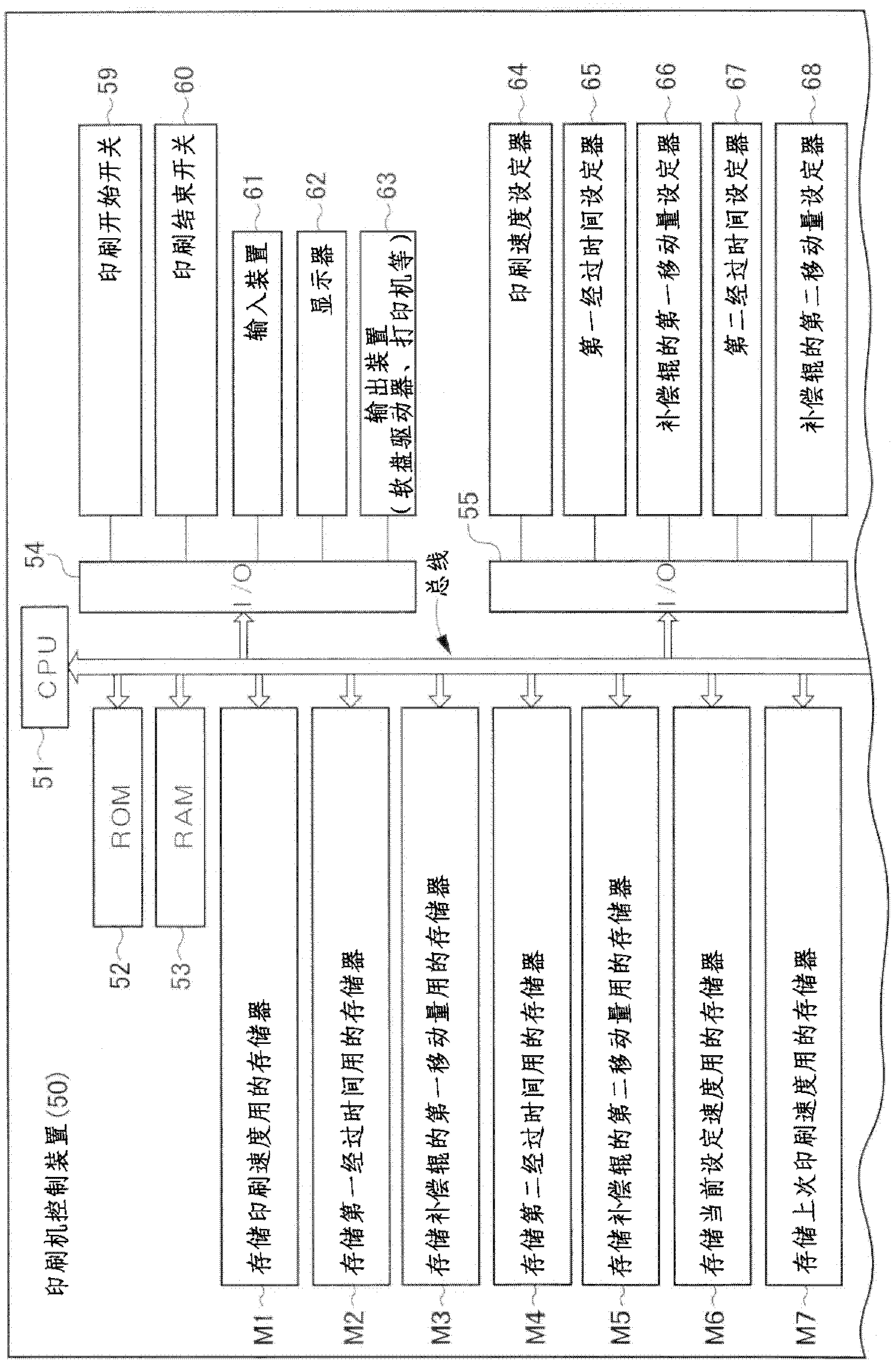
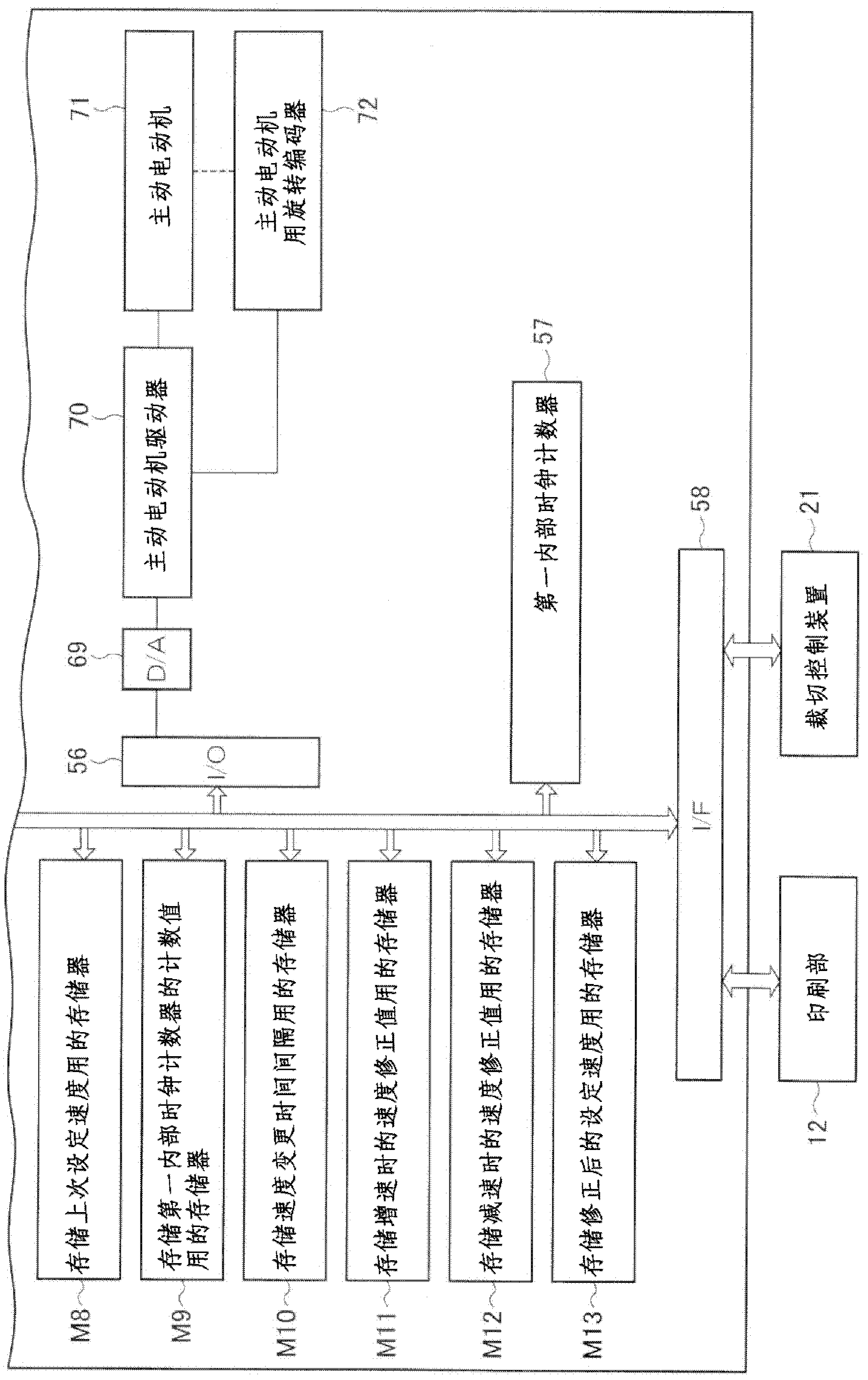
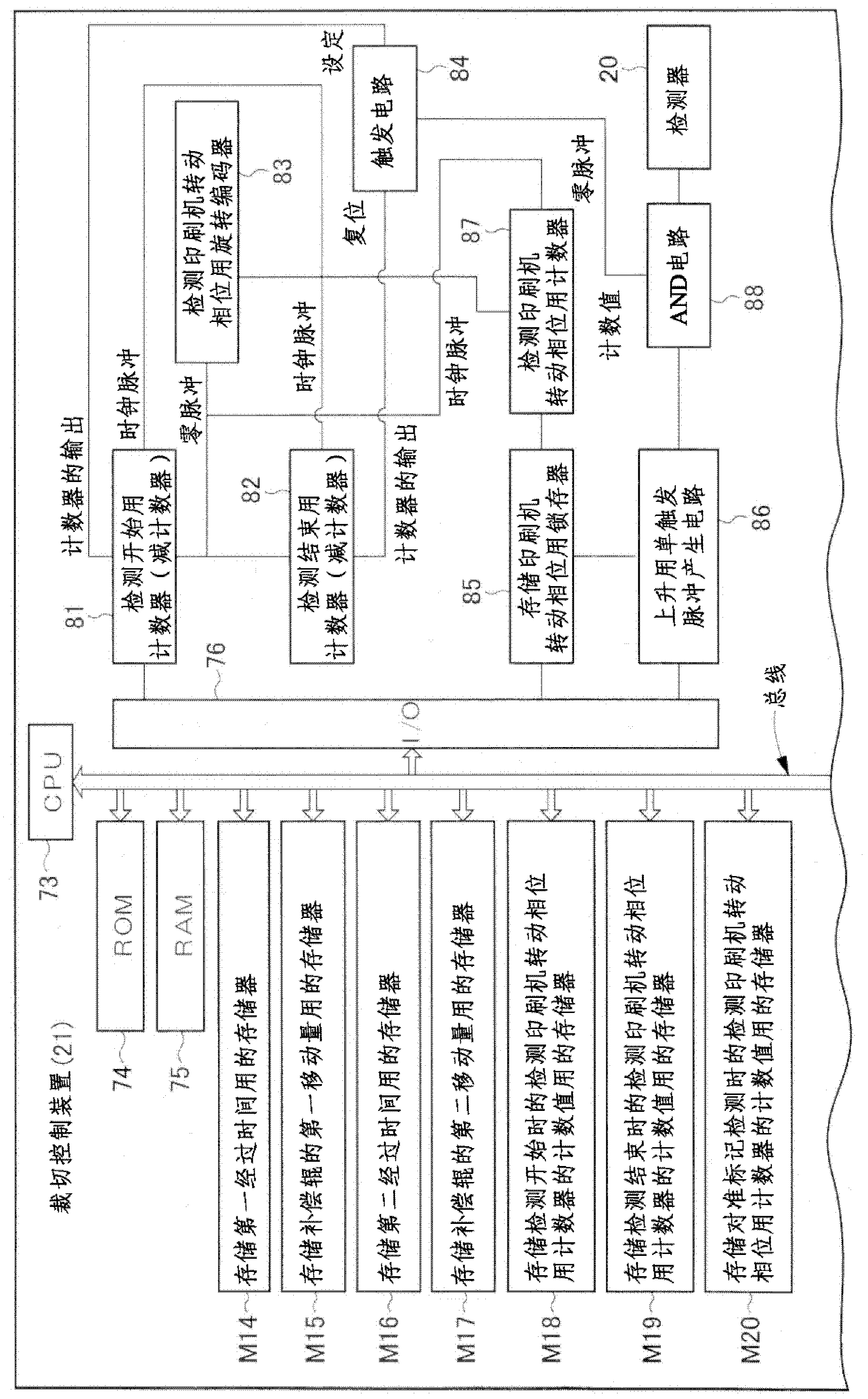
[0059] Figure 1A and Figure 1B is a block diagram showing a printing press control device according to an embodiment of the present invention, Figure 2A and Figure 2B is the block diagram of the cutting control device, Figure 3A to Figure 3E It is the flow chart of the operation of the printing machine control device, Figure 4A to Figure 4E , Figure 5A and Figure 5B , Figure 6A to Figure 6D , Figure 7A and Figure 7B It is the action flowchart of the cutting control device, Figure 8 It is a three-dimensional view of the brief structure of a web rotary press, Figure 9 It is a graph showing the operating position of the comparative compensation roller.

[0060] Such as Figure 8 As shown, the web ro...


PUM


Abstract

A printing press control device (50) and a cut-off register control device (21) forcibly move a compensator roller (19) by a set moving amount each time a set time elapses during a period from the start of speed acceleration to the end of speed acceleration.

Description

technical field [0001] The invention relates to a method and a device for adjusting the cutting position of a belt-shaped piece of a cutting device such as a cutting cylinder in a folding section of a web rotary printing machine. Background technique [0002] In the web rotary printing machine, at the center of the blank part between the printed patterns, the web is cut in the direction perpendicular to the web conveying direction by the cutting cylinder in the folding machine, Afterwards, it is folded into a folded sheet and discharged, but during the speed-up of the web rotary printing machine, due to the elongation and tension changes of the web, etc., the position of cutting with the cutting cylinder is relative to the printed pattern of the web. Offset, instead of being cut in the center of the blank, the graphic is printed in an offset position when the signature is unfolded, or in the worst case, part of the graphic is cropped. [0003] Therefore, a cutting control d...

Claims


Application Information

Patent Timeline
Patent Type & Authority Applications(China)
IPC IPC(8): B41F13/56
CPCB65H2511/512B41F33/0081B26D5/34B41F13/60B26D7/2628B65H35/08B65H2801/21B41P2213/90B65H23/1882B26D7/2614Y10T83/54Y10T83/541Y10T83/543
Inventor 井上洋
Owner KOMORI CORP
Features
  • R&D
  • Intellectual Property
  • Life Sciences
  • Materials
  • Tech Scout
  • Unparalleled Data Quality
  • Higher Quality Content
  • 60% Fewer Hallucinations
Learn More