
Contraposition two-stroke engine

An engine and two-stroke technology, which is applied in the direction of engine components, combustion engines, machines/engines, etc., can solve the problems of limiting power, restricting the efficiency of working medium replacement, and long axial dimensions, so as to improve emissions and improve combustion economy. Effect

Inactive Publication Date: 2012-10-17
BEIJING INSTITUTE OF TECHNOLOGYGY
View PDF6 Cites 27 Cited by
  • Summary
  • Abstract
  • Description
  • Claims
  • Application Information

AI Technical Summary

Problems solved by technology

[0003] However, the Junkers opposed-piston two-stroke engine has two crankshafts arranged from the two ends of the cylinder block for the intake and exhaust pistons respectively, which brings major disadvantages: the axial dimension of the engine is too long, and the two crankshafts perform power output at the same time, requiring multiple gears Convergence of output power, resulting in too complicated transmission mechanism
Compared with the current supercharged engine, the TS-3 engine has a relatively low scavenging pressure, which limits the further increase of its power and restricts the improvement of the efficiency of working medium replacement; in addition, the fuel supply system of TS-3 adopts a plunger pump structure, Long injection duration, poor controllability and low fuel injection pressure are not conducive to the atomization of fuel and the formation of mixed gas in the cylinder, which restricts the further improvement of its combustion efficiency and the further optimization of emission performance
Obviously, the Roots ts-3 engine can no longer meet the current requirements for low fuel consumption, low emission, and high power performance indicators of the engine

Method used


Image

  • Contraposition two-stroke engine
  • Contraposition two-stroke engine
  • Contraposition two-stroke engine

Examples


Embodiment Construction

[0075] In order to make the objectives, technical solutions, and advantages of the present invention clearer, the following further describes the present invention in detail with reference to the accompanying drawings and embodiments. It should be understood that the specific embodiments described here are only used to explain the present invention, but not to limit the present invention.

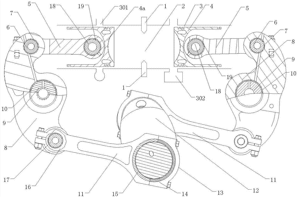
[0076] As a specific embodiment of the present invention, it includes a crank connecting rod mechanism, an intake and exhaust system, an oil supply system, a lubrication system, and a cooling system; the fixed part of the crank connecting rod mechanism includes a body and a cylinder liner, and the crank connecting rod The moving part of the rod mechanism includes an intake piston and an exhaust piston that are placed in the cylinder liner to reciprocate and are arranged in a top-facing manner. The upper connecting rod and the rocker are located on the same side as the intake piston and the exha...


PUM


Abstract

The invention discloses a contraposition two-stroke engine comprising a cylinder, a cylinder sleeve, an intake piston and an exhaust piston, upper connection rods, rocker arms, lower connection rods, and crankshafts, wherein the upper connection rods, the rocker arms and the lower connection rods are arranged on the same side as the intake piston and the exhaust piston; the cylinder sleeve and the top surfaces of the intake piston and the exhaust piston form a combustion chamber; the upper connection rods, the rocker arms and the lower connection rods on both sides are respectively arranged symmetrically; the rocker arms on both sides are respectively connected with the cylinder body by the respective rocker arm shafts; the intake piston is connected with the upper end of the rocker arm on the same side by the upper connection rod; the lower end of the rocker arm on the same side with the intake piston is connected with the crankshaft arranged right below the cylinder body by the lower connection rod on the same side with the intake piston; the connection relations between the exhaust piston and the upper connection rod, between the exhaust piston and the rocker arm, and between the exhaust piston and the lower connection rod on the same side are the same as those between the intake piston and the upper connection rod, between the intake piston and the rocker arm and the between the intake piston and the lower connection rod; the reciprocations of the intake piston and the exhaust piston drive the crankshafts by the rocker arms, the upper connection rods and the lower connection rods on the same sides. With the adoption of the engine, the shortages of the contraposition two-stroke engine are made up effectively.

Description

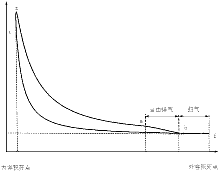
Technical field [0001] The invention relates to the field of power technology, in particular to an opposed two-stroke engine. Background technique [0002] The opposed-piston two-stroke engine has experienced a long period of development from the invention of Hugo Junkers in the late 19th century. Compared with the traditional two-stroke and four-stroke internal combustion engines, the opposed-piston two-stroke engine eliminates the need for cylinder heads, valve trains, etc. Complex parts have the advantages of simple structure, few parts, high reliability, high thermal efficiency, and high power density. Therefore, they have been widely used in occasions with high power density requirements. In the 1930s and 1940s, the Junkers opposed-piston two-stroke engine was once used as the power unit of the aircraft with its higher power density than traditional diesel engines. The principle of the Junkers engine is as follows figure 1 As shown, the two pistons are arranged in a horizont...

Claims


Application Information

Patent Timeline
Patent Type & Authority Applications(China)
IPC IPC(8): F02B75/28F02B75/02F02B75/32F02F1/22F02B23/02F02B37/04
CPCY02T10/125Y02T10/144Y02T10/12
Inventor 赵振峰张付军赵长禄章振宇董雪飞
Owner BEIJING INSTITUTE OF TECHNOLOGYGY
Learn More