Gaseous flow separator with device for thermal-bridge defrosting

An air flow separator and air separation technology, applied in jet propulsion, climate sustainability, gas turbine installations, etc., can solve problems such as failure, lubricant leakage, technical complexity, etc., and achieve simple components, rapid assembly, and simple assembly. Effect

Inactive Publication Date: 2012-10-17
SAFRAN AERO BOOSTERS SA
View PDF8 Cites 15 Cited by
  • Summary
  • Abstract
  • Description
  • Claims
  • Application Information

AI Technical Summary

Problems solved by technology

As in the aforementioned patent, this arrangement is technically complex and can ...

Method used


Image

  • Gaseous flow separator with device for thermal-bridge defrosting
  • Gaseous flow separator with device for thermal-bridge defrosting
  • Gaseous flow separator with device for thermal-bridge defrosting

Examples


Embodiment Construction

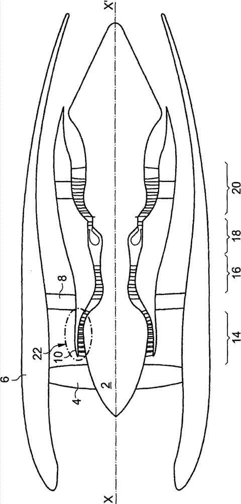
[0032] exist figure 1 A twin-flow turbojet engine is schematically shown in . It shows the main elements, namely the nacelle 6 acting as an external casing around the components, the rotor 2 rotating about the axis X-X' of the machine and the fan 4 supported by the rotor 2 .

[0033] In the following description, the terms "upstream" and "downstream" refer to an axial position along the axis X-X' in the direction of the air flow through the jet engine. The term "front" is equivalent to "upstream" and "rear" is equivalent to "downstream".

[0034] The terms "inner" or "inner", and "outer" or "outer" refer to a radial position relative to the axis XX' of the turbine, "outer" or "outer" meaning a position away from said axis and "Inner" or "inner" means a position near the axis.

[0035] Downstream of the fan 4, the airflow is divided by a splitter tip 10 into a primary and a secondary airflow. The main air flow passes through the inner annular main duct or main flow path to ...


PUM


Abstract

The invention relates to a gas flow separator dividing the flow into a primary and a secondary stream, especially for a dual rotor axial turbomachine. The separator 10 comprises a splitter nose of the turbomachine and includes a generally wedge-shaped leading edge 30 in the gas flow to be split. The flow separator also comprises a metal blade 38 having a longitudinal section in the form of an S and located in the nose in contact with the back of the leading edge 30 and extending from the leading edge 30 to a rear end of the separator 10 at some distance from the leading edge, so as to be in contact with a heat source 24, such as a heat exchanger, located at some distance from the leading edge.

Description

technical field [0001] The present invention is concerned with the problem of icing on surfaces that separate a gas flow, such as air, into a primary flow and a secondary flow. Separators of this type are used in particular in inlet compressors of twin rotor axial turbines. In this type of machine, the incoming flow is separated into primary and secondary flows. The main flow, usually annular in cross-section, flows through the engine's various compression stages, combustion chambers and turbines. The secondary flow, generally annular in cross-section, larger in diameter than and concentric with the primary flow, is compressed by the fan and the secondary flow stator and then rejoins the primary flow, contributing to thrust. Background technique [0002] The secondary flow that separates from the primary airflow after passing the intake fan can cause icing on the leading edge of the secondary airflow directing surface. This airflow is not subject to any heating and its bo...

Claims


Application Information

Patent Timeline
IPC IPC(8): F02C7/047F04D29/58
CPCF05D2260/20F02C7/047F01D25/02Y02T50/676Y02T50/60Y10T137/4245
Inventor D·巴朱兹Y·库洛特N·莱马克斯M·斯特伦纳特A·斯特法尼A·科内特G·布罗尔斯D·德佩普
Owner SAFRAN AERO BOOSTERS SA
Why Eureka
Try Eureka