
Engine flywheel assembly with gearbox starting bearing

A gearbox and engine technology, applied in the field of engine parts, can solve the problems of increased engine volume, weight, external dimensions, and complex engine structure layout, etc., to achieve convenient layout and signal collection, enhanced strength and rigidity, and convenient layout Effect

Inactive Publication Date: 2012-10-17
东风朝阳朝柴动力有限公司
View PDF5 Cites 2 Cited by
  • Summary
  • Abstract
  • Description
  • Claims
  • Application Information

AI Technical Summary

Problems solved by technology

However, with the development of diesel engine technology, the application of high-pressure common rail electronically controlled diesel engines, the arrangement of sensors and the collection of signals complicate the structural arrangement of the engine, and many accessories are added, which increases the volume, weight, and overall dimensions of the engine. Simplify the structural arrangement of the engine, and propose the engine flywheel assembly

Method used


Image

  • Engine flywheel assembly with gearbox starting bearing
  • Engine flywheel assembly with gearbox starting bearing

Examples


Embodiment Construction

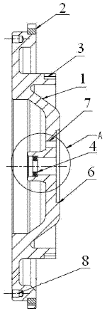
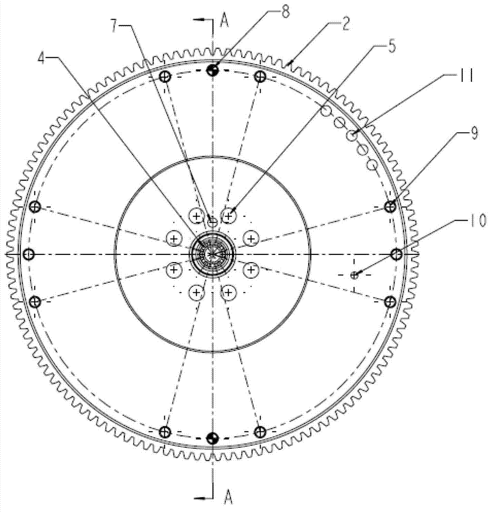
[0009] The principle and structure of the present invention will be further described below with reference to the accompanying drawings and through specific embodiments. The engine flywheel assembly with the gearbox starting bearing has a structure that the outer ring of the flywheel 1 is inlaid with the starting ring gear 2, and the outer end surface of the flywheel is processed with tooth grooves 3. The center hole of the flywheel is inlaid with a thrust bearing 4, and the outer circumference of the center hole is provided with 8 large threaded holes 5 symmetrically distributed and used for fixing the crankshaft. Pin hole 7. There is a large pin hole 8 on the inner end surface of the flywheel, 12 small threaded holes 9 symmetrically distributed and fastened to the clutch are arranged on the circumference of the outer end surface of the flywheel, and a positioning hole 10 is arranged on the outer end surface of the flywheel between the small threaded holes and the stop . Fi...


PUM


Abstract

The invention discloses an engine flywheel assembly with a gearbox starting bearing. The engine flywheel assembly is structurally characterized in that a starting gear ring is inlaid on an outer ring of a flywheel; a tooth socket is processed on an outer end face of the flywheel; and a thrust bearing is inlaid in a central hole of the flywheel. 8 symmetrically distributed large threaded holes fixed with a crank shaft are arranged on an outer circumference of the central hole; a seam allowance is processed on an outer end face of the central hole and is internally provided with a small pin hole; and a large pin hole is arranged in an inner end face of the flywheel. 12 symmetrically distributed small threaded holes fixed with a clutch are arranged on a circumference of an outer end face of the flywheel; and a locating hole is arranged in the outer end face of the flywheel between the small threaded holes and the seam allowance. The flywheel is provided with the starting bearing, and a coded disc of an ECU (Engine Control Unit) for collecting crankshaft speed signals, so that when an engine is primarily assembled, fuel feed and valve timing are ensured, the functions of a traditional flywheel are realized, and meanwhile, the gearbox starting bearing of an automobile is supported.

Description

technical field [0001] The invention belongs to engine components, in particular to an assembly structure of an engine flywheel. Background technique [0002] The main function of the engine flywheel is to use part of the energy of the crankshaft to overcome the resistance generated by the compression, intake and exhaust of the engine cylinder, so as to make the crankshaft speed and torque output as uniform as possible, and prevent the engine from stalling when idling and starting. , and make the engine have the ability to overcome short-term overload. The assembly structure of the general engine flywheel is that the outer edge of the flywheel is pressed into the ring gear, and the flywheel meshes with the starter ring gear to drive the engine to start and run. However, with the development of diesel engine technology, the application of high-pressure common rail electronically controlled diesel engines, the arrangement of sensors and the collection of signals complicate th...

Claims


Application Information

Patent Timeline
IPC IPC(8): F16F15/30
Inventor 陈玉荣李晓刚张宏辉赵霄鹏张学存李长水乌永波张俊波蔡旭冰
Owner 东风朝阳朝柴动力有限公司
Learn More