LED (light-emitting diode) backlight module

A technology of backlight module and LED light bar, which is applied in the direction of optics, light guide, light source, etc., can solve the problems of damage to the light guide plate, affect the backlight efficiency, and increase the distance between the light guide plate and LED, so as to ensure the coupling distance and improve the Effect of coupling efficiency

Active Publication Date: 2012-10-17
TCL CHINA STAR OPTOELECTRONICS TECH CO LTD
View PDF5 Cites 35 Cited by
  • Summary
  • Abstract
  • Description
  • Claims
  • Application Information

AI Technical Summary

Problems solved by technology

Such a variation will have two risks: ① LED reliability risk, LED will be damaged by light guide plate; warping
[0008] In the prior art, in order to avoid warping of the light guide plate due to thermal expansion or moisture absorption expansion, it is necessary to reserve enough movement for the light guide plate, so that the distance between the light guide plate and the LED becomes larger, so that the light coupling distance will decrease. reduce, greatly affecting the efficiency of the backlight

Method used


Image

  • LED (light-emitting diode) backlight module
  • LED (light-emitting diode) backlight module
  • LED (light-emitting diode) backlight module

Examples


Embodiment Construction

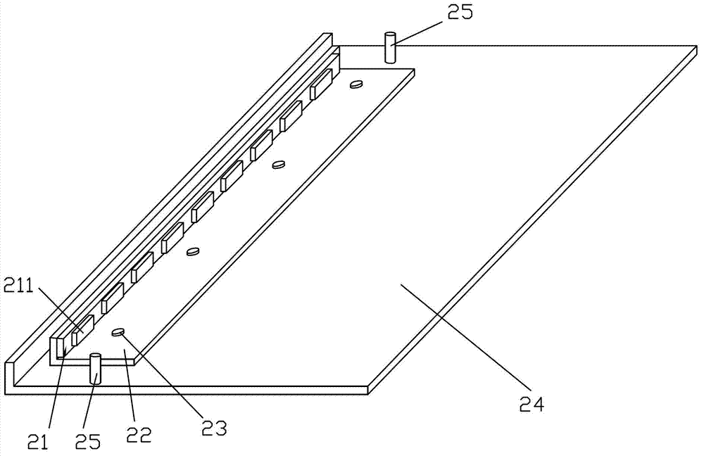
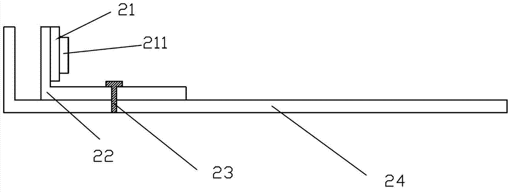
[0036] see Figure 6 to Figure 10 , Figure 6 It is a three-dimensional schematic diagram of a backplane of a preferred embodiment of the LED backlight module of the present invention; Figure 7 for Figure 6 Top view of the mid-backplane; Figure 8 It is a three-dimensional schematic diagram after removing the light guide plate for a preferred embodiment of the LED backlight module of the present invention; Figure 9 It is a top view of the light guide plate of a preferred embodiment of the LED backlight module of the present invention; Figure 10 It is an assembly diagram of a preferred embodiment of the LED backlight module of the present invention.

[0037] The LED backlight module of the present invention mainly includes a light guide plate 30, an LED light bar 31, a back plate 32, and a heat sink 33. The LED light bar 31 is fixed on the heat sink 33 adjacent to the light incident side of the light guide plate 30, and There is an upwardly extending light guide plate ...


PUM


Abstract

The invention relates to an LED (light-emitting diode) backlight module which comprises a light guide plate, an LED lamp bar, a back plate and a heat radiating element, wherein the light incoming side edge of the LED lamp bar, which is close to the light guide plate, is fixed on the heat radiating element; the heat radiating element is provided with a light guide plate positioning post which is relatively fixed on the heat radiating element and extends upward; the light guide plate positioning post penetrates through the light guide plate upward, thus the light guide plate is relatively positioned on the heat radiating element; the heat radiating element is movably arranged on the back plate along the light incoming direction; and the heat radiating element shifts along with the expansion or shrinkage of the light guide plate so as to keep the light coupling distance between the light guide plate and the LED lamp bar. The LED backlight module provided by the invention can prevent the light guide plate from warping caused by mechanism interference after the light guide plate is expanded by heating or moisture absorption, can prevent the light guide plate from being collided with LEDs after the light gudie plate is expanded because of heating or moisture absorption so as to avoid invalidity, and can guarantee the light coupling distance between the light guide plate and the LEDs so as to improve the light coupling efficiency.

Description

technical field [0001] The invention relates to liquid crystal display technology, in particular to an LED backlight module. Background technique [0002] Existing LED backlight modules used in liquid crystal display technology are mainly divided into direct-type backlight modules and side-type backlight modules. For side-lit LED backlight modules, with the continuous improvement of LED efficiency, the design of LED backlights has also continued to evolve, from the initial four-side light input, to double-side light input, to single-side light input, current development and future development. The direction of all will point to the single short side light incident mode. [0003] The side-type LED backlight is to arrange the LED crystal grains around the edge of the LCD panel, and then match the light guide plate, so that when the LED backlight is illuminated in partitions, the light emitted from the edge of the LCD panel passes through the light guide plate (LGP) It is sen...

Claims


Application Information

Patent Timeline
Patent Type & Authority Applications(China)
IPC IPC(8): F21S8/00F21V17/10F21Y101/02
CPCG02B6/0068G02B6/0085G02B6/0091G02B6/0001
Inventor 贺虎
Owner TCL CHINA STAR OPTOELECTRONICS TECH CO LTD
Why Eureka
Try Eureka