Measuring device and measuring method for straight cone gear pitch cone angle

A technology of bevel gears and measuring devices, applied in angle/taper measurement, etc., can solve problems affecting gear interchangeability, difficulty in accurately measuring the actual angle of straight bevel gear pitch cone angle, direct measurement and detection, which troubles engineers and technicians, etc. problem, to achieve the effect of verifying machining accuracy, low manufacturing cost, and small volume

Inactive Publication Date: 2012-10-17
陕西工业职业技术学院
View PDF4 Cites 8 Cited by
  • Summary
  • Abstract
  • Description
  • Claims
  • Application Information

AI Technical Summary

Problems solved by technology

However, the pitch cone angle of straight bevel gears is the contact cone angle produced when a bevel gear meshes with another bevel gear with only pure rolling but no sliding. It is a spatial angle, and the direct measurement and detection of its angle has always troubled engineering technology personnel
[0003] At present, the factory still uses an approximate method to measure the pitch angle of the spur bevel gear. Specifically, a gear pairing machine or a double gear instrument is used to mesh and roll the paired bevel gears. If there is no paired gear, it is necessary to manufacture a calibration gear to For rolling, judge the contact condition of the pitch cone by observing the contact spots. This method is difficult to accurately measure the actual angle of the pitch cone angle of the spur bevel gear, which will directly affect the interchangeability of the gear.

Method used


Image

  • Measuring device and measuring method for straight cone gear pitch cone angle
  • Measuring device and measuring method for straight cone gear pitch cone angle
  • Measuring device and measuring method for straight cone gear pitch cone angle

Examples


Embodiment Construction

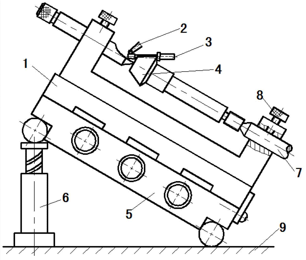
[0027] refer to figure 1 and combine Figure 5 , to illustrate the specific structure of the measuring device of the spur bevel gear of the present invention. The device for measuring the pitch cone angle of the spur bevel gear of this embodiment mainly includes a test rod 3 paired with the standard tooth groove of the spur bevel gear to be tested, a measuring platform 9, and a lever dial gauge 2 placed on the measuring platform 9 , the sine gauge 5 and the adjustable contour block 6 that cooperates with the sine gauge 5 to measure the angle, the upper plane of the sine gauge 5 is provided with the top frame 1 for clamping the straight bevel gear to be tested, and the left and right tops of the top frame are required The connecting line is parallel to the upper plane of the sine gauge.

[0028] Set the top frame 1 on the sine gauge 5, fix the straight bevel gear 4 to be tested on the top frame 1 with the left and right tops 7, the left top here is set as a half top, and the ...


PUM


Abstract

The invention relates to a straight cone gear measuring technology and discloses a measuring device and a measuring method for a straight cone gear pitch cone angle. The device comprises a test rod matching with standard tooth space of a straight cone gear to be measured, a measuring platform, a fine dial test indicator located on the measuring platform, a sine bar and an adjustable equal-height block, wherein the equal-height block is in cooperation with the sine bar to measure angles; a center rest used for clamping the straight cone gear to be measured is arranged on an upper plane of the sine bar; a connection line between a left center and the right center of the center rest is in parallel with the upper plane of the sine bar; a contact cone is in a center portion of the test rod; two ends of the contact cone are provided with a first measuring circular column and a second measuring circular column, wherein the two measuring circular columns are with a same diameter; an axial line of the two measuring circular columns coincides with a center line of the contact cone. According to the invention, the measuring device has advantages of a small volume, low manufacturing cost and convenient operation; the measuring method has advantages of simple operation, high measuring precision and high efficiency, and measuring in a production field can be realized by using the method.

Description

technical field [0001] The invention relates to a straight bevel gear measuring technology, in particular to a measuring device and a measuring method for the pitch angle of a straight bevel gear. Background technique [0002] Bevel gears are widely used in machine tools, automobiles, mines, construction and other mechanical equipment. Straight-toothed bevel gear is an important part of the grinding machine. The accuracy of its pitch cone angle directly affects the noise, strength, contact area of ​​the tooth surface and the stability of the gear transmission when the gear is meshing. It is an important parameter that affects the quality of the gear. . Therefore, the accuracy of pitch angle measurement of spur bevel gear directly affects the processing quality of the gear. However, the pitch cone angle of straight bevel gears is the contact cone angle produced when a bevel gear meshes with another bevel gear with only pure rolling but no sliding. It is a spatial angle, and...

Claims


Application Information

Patent Timeline
Patent Type & Authority Applications(China)
IPC IPC(8): G01B5/24
Inventor 郭新玲田俊成
Owner 陕西工业职业技术学院
Why Eureka
Try Eureka