Inductive current detecting circuit and LED (light emitting diode) driving circuit using inductive current detecting circuit

A technology of LED drive and voltage detection circuit, applied in the field of electronics, can solve the problems of low output current control accuracy, low power factor, unsatisfactory power factor correction of LED drive circuit, etc., and achieves low cost, small size and high reliability. sexual effect

Active Publication Date: 2012-10-17
SILERGY SEMICON TECH (HANGZHOU) CO LTD
View PDF7 Cites 54 Cited by
  • Summary
  • Abstract
  • Description
  • Claims
  • Application Information

AI Technical Summary

Problems solved by technology

However, sampling this implementation method only samples the current of the power switch tube Q1 and does not directly sample the load current, so the output current control accuracy is not high; moreover, the power factor correction of the above-mentioned LED drive circuit is not ideal, and the power factor is not good. high

Method used


Image

  • Inductive current detecting circuit and LED (light emitting diode) driving circuit using inductive current detecting circuit
  • Inductive current detecting circuit and LED (light emitting diode) driving circuit using inductive current detecting circuit
  • Inductive current detecting circuit and LED (light emitting diode) driving circuit using inductive current detecting circuit

Examples


Embodiment Construction

[0046] Several preferred embodiments of the present invention will be described in detail below with reference to the accompanying drawings, but the present invention is not limited to these embodiments. The present invention covers any alternatives, modifications, equivalent methods and schemes made on the spirit and scope of the present invention. In order to provide the public with a thorough understanding of the present invention, specific details are set forth in the following preferred embodiments of the present invention, but those skilled in the art can fully understand the present invention without the description of these details.

[0047] The inductor current detection circuit according to the present invention will be described in detail below in conjunction with specific embodiments.

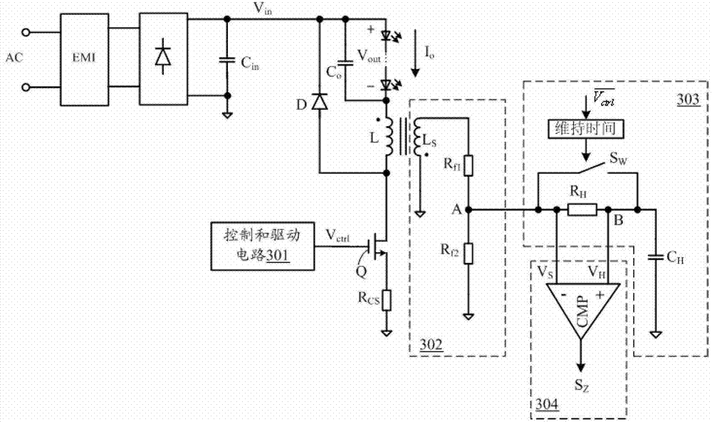
[0048] refer to Figure 3A , shows a functional block diagram of an inductor current detection circuit according to an embodiment of the present invention. In this embodiment, the...


PUM


Abstract

The invention relates to an inductive current detecting circuit in a switch power supply and an LED (light emitting diode) driving circuit using the inductive current detecting circuit. According to the inductive current detecting circuit provided by the embodiment of the invention, an inductive current ending time in an interrupted working mode of the inductive current can be detected precisely through a voltage sampling and holding circuit so that inductive current duration time can be obtained precisely. According to the LED driving circuit provided by the embodiment of the invention, with the adoption of the inductive current detecting circuit, an inductive current average value can be obtained precisely, i.e. output current information of the LED driving circuit can be obtained precisely, so that the current control precision is improved; furthermore, the power factor calibration is realized; and a higher power factor is obtained.

Description

technical field [0001] The invention relates to the field of electronic technology, more specifically, to an inductor current detection circuit in a switching power supply and an LED driving circuit using the same. Background technique [0002] With the continuous innovation and rapid development of the lighting industry, coupled with the increasing importance of energy saving and environmental protection, LED lighting, as a revolutionary energy-saving lighting technology, is developing rapidly. However, due to the volt-ampere characteristics and temperature characteristics of the LED itself, the sensitivity of the LED to the current is higher than the sensitivity to the voltage, so the traditional power supply cannot directly supply power to the LED. Therefore, to use LED as a lighting source, we must first solve the problem of power drive. Although the traditional LED drive power supply can realize LED brightness adjustment, it cannot realize power factor correction, the ...

Claims


Application Information

Patent Timeline
Patent Type & Authority Applications(China)
IPC IPC(8): G01R19/00H05B37/02H05B44/00
CPCY02B20/347H02M2001/0009H05B33/0815H05B33/0806Y02B20/42H02M7/12H05B45/375Y02B20/30H05B45/345H05B45/3725H05B45/355H02M1/0009
Inventor 徐孝如
Owner SILERGY SEMICON TECH (HANGZHOU) CO LTD
Why Eureka
Try Eureka