
Stereoscopic image display system and its liquid crystal parallax barrier

A liquid crystal parallax grating and grating technology, applied in the field of gratings, can solve the problems of inability to display stereoscopic images normally, crosstalk between left and right eye images, and limited grating distance, so as to increase the viewing angle and viewing distance, reduce the number of driving paths, and increase the The effect of large viewing distances

Active Publication Date: 2016-01-13
TRULY SEMICON
View PDF2 Cites 2 Cited by
  • Summary
  • Abstract
  • Description
  • Claims
  • Application Information

AI Technical Summary

Problems solved by technology

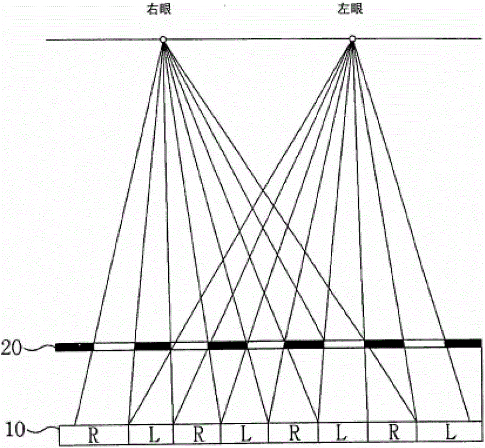
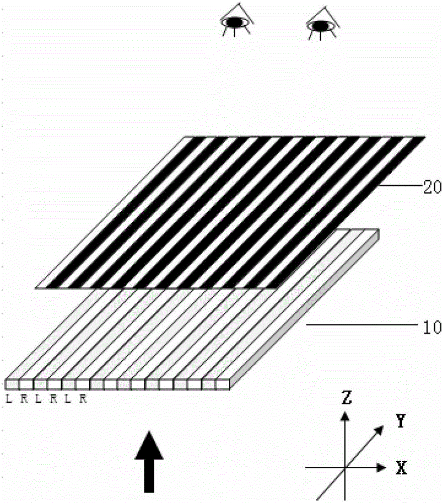
[0004] However, the stereoscopic image display system based on the above-mentioned liquid crystal parallax barrier has certain defects, which are manifested in the following aspects: (1) The current general-purpose display screens are all based on the RGB color filter display method, and a pixel is placed along the horizontal direction ( figure 2 The X direction in the image) is divided into three parts R, G, and B on average, and R, G, and B are called sub-pixels
However, the conventional liquid crystal grating parallax barrier sometimes happens that part of R, G or B is blocked by the setting or thickness of the grating 20, so it cannot be seen, resulting in the failure to display stereoscopic images normally
(2) Another problem with the conventional liquid crystal parallax barrier is that the thickness of the grating and the distance between the gratings are limited. When the distance and angle limit are exceeded, it will cause crosstalk between the left and right eye images, and the viewing distance is limited to a specific length.
Then, the problem with the conventional method is that the light emitted from the display screen is blocked, causing the brightness of the light emitted from the display module to be reduced to a rather low level after passing through the conventional liquid crystal barrier.

Method used


Image

  • Stereoscopic image display system and its liquid crystal parallax barrier
  • Stereoscopic image display system and its liquid crystal parallax barrier
  • Stereoscopic image display system and its liquid crystal parallax barrier

Examples


Embodiment Construction

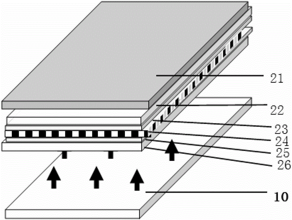
[0030] In the preferred embodiment of the liquid crystal parallax barrier of the present invention, it includes: a liquid crystal layer (LC layer), the liquid crystal layer is placed in a box-shaped space, and is divided into a box matrix structure pixel by a control electrode, and a horizontal or vertical direction is formed by a predetermined control method. The grating; the control electrode, the control electrode is divided into the upper control electrode and the lower control electrode, the control electrodes are made into long strips, and the upper / lower control electrodes are set as pixels in a box-shaped matrix structure, so as to selectively The state of the LC layer is controlled to be turned on or off to form a grating pattern in the horizontal or vertical direction; the lower substrate is formed between the LC layer and a predetermined display module, so that the liquid crystal layer and the control electrode are arranged at a distance from the display module at a ...


PUM

PropertyMeasurementUnit
angleaaaaaaaaaa

Abstract

The invention relates to a grating technology, in particular to a three-dimensional image display system and a liquid crystal parallax grating thereof. According to the liquid crystal parallax grating, a liquid crystal layer is partitioned into box-type matrix structure pixels by an upper / lower control electrode to form a grating in a horizontal or perpendicular direction; the upper / lower control electrode is manufactured to be elongated so as to be arranged into the box-type matrix structure pixels respectively and selectively switched on and switched off to control a state of the liquid crystal layer, thus forming a grating pattern in the horizontal or perpendicular direction; a lower substrate is formed between the liquid crystal layer and a display module; an upper substrate is arranged at the tops of the liquid crystal layer and the upper control electrode; and a polarizer is arranged at the top of the upper substrate and / or at the bottom of the lower substrate and used for controlling the on / off state of the pixels according to a polarization angle, so that the grating pattern is visible. The three-dimensional image display system comprises the display module and the liquid crystal parallax grating. According to the liquid crystal parallax grating, the grating is perpendicularly or horizontally converted, so that the visible angle and the watching distance of the three-dimensional image display system can be enlarged.

Description

technical field [0001] The invention relates to grating technology, in particular to a stereoscopic image display system and a liquid crystal parallax grating. The liquid crystal parallax grating includes TN type liquid crystal cells formed in a matrix structure. Background technique [0002] At present, information communication technology has been developed to a high level, and digital terminals can process text, voice and image information at a very high speed to provide multimedia content services with two-dimensional images and voice. The next development direction is three-dimensional information service, which can provide three-dimensional multimedia service. According to the theory of binocular stereoscopic imaging, the two eyes see two different two-dimensional images respectively. When the two images are transmitted to the brain through the retina, the brain combines the two transmitted images and reproduces the image with a sense of depth and reality. 3D image. ...

Claims


Application Information

Patent Timeline
Patent Type & Authority Patents(China)
IPC IPC(8): G02F1/1343G02F1/1337G02F1/1335G02F1/133G02B27/26H04N13/04G02B30/25
Inventor 吴梓平王新志周晓峰伍小丰何基强
Owner TRULY SEMICON
Learn More