Touch panel device

A technology of touch screen and touch position, which is applied in the direction of instruments, electrical digital data processing, and input/output process of data processing, etc. It can solve the problems of higher possibility of misoperation, multi-infrared light sensors, and increased number of parts, etc. Achieve the effect of suppressing misoperation and improving detection sensitivity

Inactive Publication Date: 2012-10-17
MITSUBISHI ELECTRIC CORP
View PDF7 Cites 9 Cited by
  • Summary
  • Abstract
  • Description
  • Claims
  • Application Information

AI Technical Summary

Problems solved by technology

[0005] However, in the device of Patent Document 1, since the resolution of the touch input is determined by the number of infrared sensors, in order to accurately detect the position of the pointing unit, many infrared sensors are required, and there is a problem that the number of parts increases.
[0006] In addition, in the devices described in Patent Document 2 and Patent Document 3, although the counter substrate is used as a capacitive touch panel device, the influence of the change in the detection capacitance according to the type of the pointing unit is not fully considered.
Therefore, when the fingers and fingernails of a gloved hand, whose detection capacitance is lower than that of a bare hand, are used as the pointing unit, the detection sensitivity must be improved, and there are problems such as receiving ambient noise such as static sparks, The possibility of malfunction increases due to the influence of moisture such as dew condensation on the contact surface

Method used


Image

  • Touch panel device
  • Touch panel device
  • Touch panel device

Examples


Embodiment approach 1

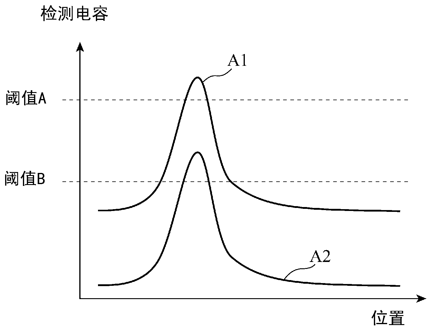
[0022] In the capacitive touch panel device, the touch position is specified by detecting the capacitance at the pressed position of the pointing unit on the touch surface.

[0023] figure 1 It is a graph showing the relationship between the pressed position on the touch surface and the detected capacitance in the capacitive touch panel device. Such as figure 1 As shown, the touch input is detected according to whether the detection capacitance exceeds a specified threshold. The detection capacitance has a characteristic that is greatly affected by the type of pointing unit. Usually, the threshold value A is set assuming the capacitance characteristic A1 generated by a touch input with a bare finger.

[0024] On the other hand, in recent years, it is desired to be able to detect the wearing of gloves and the touch operation using a fingernail (pawl), which hardly cause a change in capacitance. In this case, since the capacitive characteristic A2 has a detection capacitance ...

Embodiment approach 2

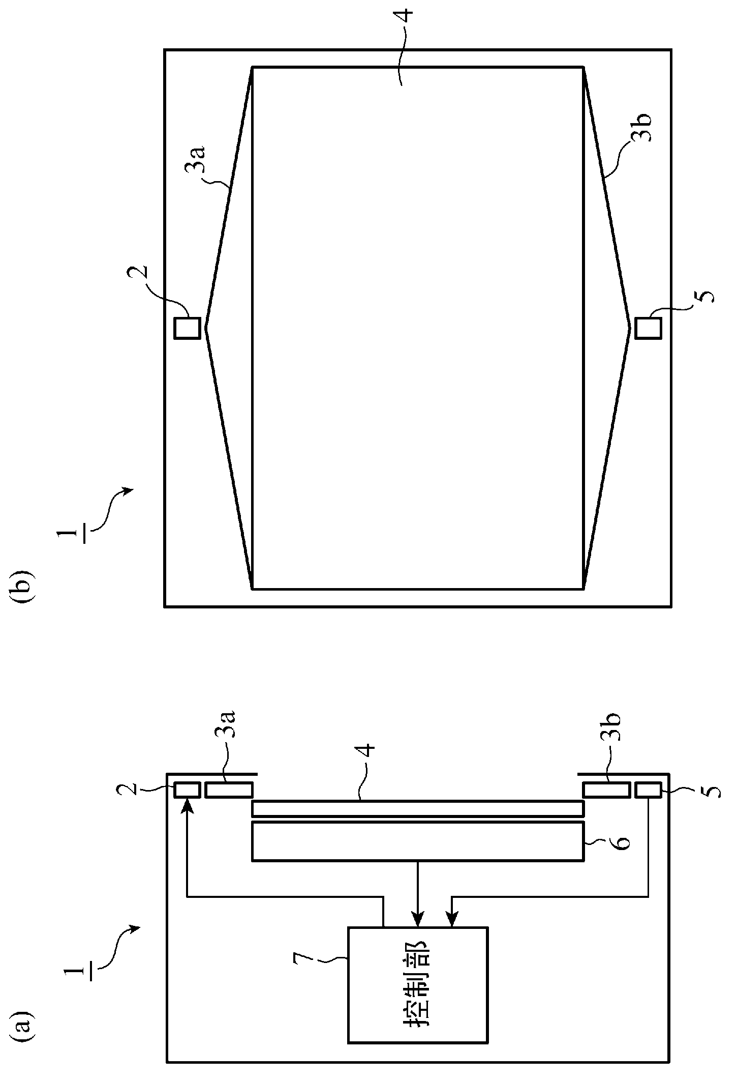
[0038] Figure 4 It is a figure showing the structure of the touch panel device concerning Embodiment 2 of this invention. Such as Figure 4 As shown, touch panel device 1A according to Embodiment 2 includes movable glass 8 , movable glass side transparent electrode 9 a , fixed glass side transparent electrode 9 b , touch panel 4 , liquid crystal module 6 , and control unit 7 . Like Embodiment 1, the touch panel 4 is configured by including detection electrodes on the touch surface side and drive electrodes disposed opposite to the detection electrodes with a glass substrate interposed therebetween. An electrostatic capacitance is formed between the detection electrodes and the drive electrodes, and the static electricity Touch is detected when the capacitance changes due to the approach or contact of the pointing unit. The touch panel 4 is fixedly arranged on the liquid crystal module 6 as a fixed glass. The liquid crystal module 6 is disposed opposite to the touch panel 4...


PUM


Abstract

Disclosed is a touch panel device in which touch position detection employing an electrostatic capacitance system of a touch panel (4) is carried out upon detection of shielding of infrared light irradiated onto a touch screen.

Description

technical field [0001] The present invention relates to a touch screen device that detects a touch position in an electrostatic capacitance method. Background technique [0002] As a conventional touch panel device, there is a device disclosed in Patent Document 1, for example. The device includes an infrared light sensor for detecting infrared light, and the infrared light sensor detects reflected infrared light generated by reflecting infrared light for detection by a pointing unit such as a finger, and infrared light included in external light. The received light signals corresponding to the reflected infrared light detected by the infrared light sensor and the infrared light included in the external light are processed by the light received signal processing circuit part in the device, and the processed light received signal is sent to Position detection / light intensity detection circuit section. The position detection / light intensity detection circuit unit detects tha...

Claims


Application Information

Patent Timeline
Patent Type & Authority Applications(China)
IPC IPC(8): G06F3/044G06F3/042G06F3/045
CPCG06F3/0418G06F3/044
Inventor 荒木 干夫
Owner MITSUBISHI ELECTRIC CORP
Why Eureka
Try Eureka